Method for establishing one-tube multi-machine differential equation model through multi-machine form of tunnel and surge shaft

A differential equation model, surge well technology, applied in special data processing applications, instruments, electrical digital data processing, etc., can solve problems such as inconvenience in hydraulic transient applications

Active Publication Date: 2019-09-10
KUNMING UNIV OF SCI & TECH
View PDF8 Cites 4 Cited by
  • Summary
  • Abstract
  • Description
  • Claims
  • Application Information

AI Technical Summary

Problems solved by technology

With the development of nonlinear theory, the form of first-order differential equation is generally used in nonlinear analysis and control theory, and the hydraulic transient application of this transfer function form is very inconvenient

Method used


Image

  • Method for establishing one-tube multi-machine differential equation model through multi-machine form of tunnel and surge shaft
  • Method for establishing one-tube multi-machine differential equation model through multi-machine form of tunnel and surge shaft
  • Method for establishing one-tube multi-machine differential equation model through multi-machine form of tunnel and surge shaft

Examples


Embodiment 1

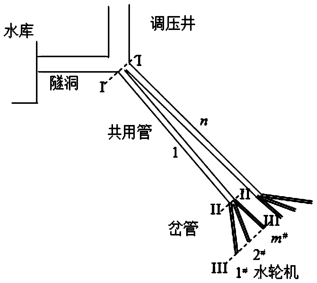
[0057] The layout and basic parameters of the hydraulic system of a power station are as follows: water is the water inlet and the surge shaft is a diversion tunnel with a diameter of 8 meters and a length of 932 meters; the height of the surge shaft is 65.8 meters and the inner diameter is 13 meters; The first penstock is 517 meters long and the second one is 490 meters long. The ends are divided into two bifurcated pipes with a diameter transitioning from 3.2 meters at the entrance to 2.2 meters to connect 4 turbines. In the simulation, No. 1 and No. 2 units share one common pipe, and No. 3 and No. 4 units share another common pipe.

[0058] Turbine parameters: H r =312m, Q r =53.5m 3 / s,P r = 150MW, n r =333.3rpm, tunnel flow inertia time constant T w =3.24376(s), surge well parameters: C s =774.06(s).

[0059] The turbine governor adopts a typical parallel PID structure, and the control parameters are: K p =5.0,K D =1.5,K I =2.5, bp=0.04, the execution cycle of t...


PUM


Abstract

The invention relates to a method for establishing a one-tube multi-machine differential equation model through a multi-machine form of a tunnel and a surge shaft, and belongs to the technical field of stability analysis and control of water turbines and hydraulic power units. N paths of steel pipes are arranged behind the surge shaft, m branch pipes are arranged at the tail end of each path of steel pipe, and the total number of the units is n * m; the hydraulic system dynamically comprises a tunnel, a surge shaft, a shared pipeline and a bifurcated pipe. The rated flow Qr and the rated waterhead Hr of the water turbine are taken as base values, the unit of Qr is 3 meters per second, and the unit of Hr is meter, the specific steps are as follows: 1. Dynamically decomposing the hydraulicpower of a tunnel and a surge shaft into a multi-machine form; and 2, constructing a differential algebraic multi-machine model of the one-pipe multi-machine belt surge shaft. The method provides a convenient calculation method and means for researching the stability of the complex hydraulic system and the hydropower station under the condition of electromechanical multi-field coupling and the multi-machine cooperative nonlinear control design of the hydropower station.

Description

technical field [0001] The invention relates to a method for establishing a multi-machine differential equation model of a pipe through the multi-machine form of a tunnel and a surge well, and belongs to the technical field of stability analysis and control of water turbines and hydraulic units. Background technique [0002] In hydropower stations with long water diversion systems, tunnels are usually used to divert water to the surge well near the powerhouse. After the surge well, steel pipes are used to divert water to the front of the powerhouse, and then several pipelines are branched out to the turbines, that is, one pipe with multiple machines. Complex diversion system for wells. The common pipeline of this complex water diversion system is the hydraulic coupling channel between multiple units of the hydropower station, and its hydraulic dynamic calculation is one of the main difficulties in the study of the stability and control design of hydropower units. [0003] A...

Claims


Application Information

Patent Timeline
Patent Type & Authority Applications(China)
IPC IPC(8): G06F17/50
CPCG06F2119/06G06F30/20Y02E10/20
Inventor 曾云钱晶吕顺利于凤荣张晓旭李丹
Owner KUNMING UNIV OF SCI & TECH
Why Eureka
Try Eureka