Solar heat dissipation device of low-voltage electric power metering box, and use method

A heat dissipation device and low-voltage power technology, which is applied in the direction of circuit devices, battery circuit devices, substation/distribution device shells, etc., can solve fires, affect the accuracy of metering devices, the insulation strength of power supply equipment, and the poor heat dissipation effect of distribution boxes, etc. problem, achieve the effect of reducing the temperature and humidity in the box

Pending Publication Date: 2019-09-10
STATE GRID JIBEI ELECTRIC POWER CO LTD TANGSHAN POWER SUPPLY CO +1
0 Cites 0 Cited by

AI-Extracted Technical Summary

Problems solved by technology

If the heat dissipation effect of the distribution box is not good, it will affect the accuracy of the metering device and reduce th...

Abstract

The invention relates to a solar heat dissipation device of a low-voltage electric power metering box and a use method of the solar heat dissipation device, and belongs to the technical field of heatdissipation of 0.4KV power supply facilities. According to the technical scheme, two solar panels (1) are mounted at the upper part of the metering box in parallel; an air supply direct-current motor(13) is mounted at the upper part of the left side of a box body of the metering box; an air draft direct-current motor (14) is mounted at the lower part of the right side of the box body of the metering box; the air supply direct-current motor (13) and the air draft direct-current motor (14) are connected with an air supply fan and an air draft fan respectively; the output ends of the solar panels (1) are connected with a lithium battery (7) through a voltage stabilizing chip (7); the output end of the lithium battery is connected with the air supply direct-current motor and the air draft direct-current motor through a temperature control switch (9); and the air supply direct-current motor and the air draft direct-current motor are connected in parallel. The device has the beneficial effects that solar power is used for generating power; the fans are driven to dissipate heat through the rotation of the direct-current motors; air in the box is subjected to convection, so that the purposes of reducing the temperature and the humidity in the box are achieved; and the energy is saved and the efficiency is high.

Application Domain

Batteries circuit arrangementsSubstation/switching arrangement cooling/ventilation +2

Technology Topic

Solar powerTemperature control +7

Image

  • Solar heat dissipation device of low-voltage electric power metering box, and use method
  • Solar heat dissipation device of low-voltage electric power metering box, and use method
  • Solar heat dissipation device of low-voltage electric power metering box, and use method

Examples

  • Experimental program(1)

Example Embodiment

[0016] The technical scheme of the present invention will be further described in detail below in conjunction with the drawings and embodiments.
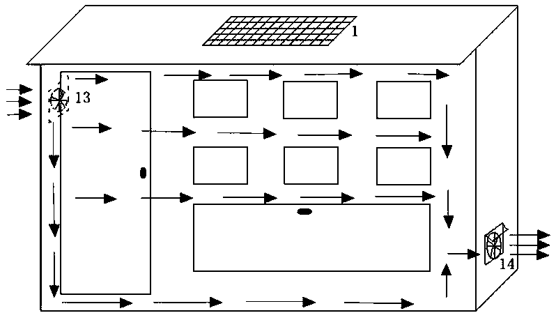
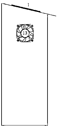
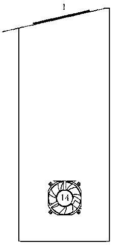
[0017] A low-voltage power metering box solar heat dissipation device, comprising a solar panel 1, a voltage stabilizing chip 5, a lithium battery 7, a temperature control switch 9, a supply air DC motor 13 and a ventilation DC motor 14. There are two solar panels 1 connected in parallel Installed on the upper part of the metering box; the air supply DC motor 13 is installed on the upper left side of the box body of the metering box, and the exhaust air DC motor 14 is installed on the lower right side of the box body of the metering box. The air supply DC motor 13 and the exhaust air DC motor 14 are respectively connected There are air supply fans and exhaust fans; the output end of the solar panel 1 is connected to the lithium battery 7 through the voltage regulator chip 5; the output end of the lithium battery 7 is connected to the air supply DC motor 13 and the exhaust air DC motor 14 through the temperature control switch 9 to supply air The DC motor 13 and the exhaust DC motor 14 are connected in parallel with each other.
[0018] A diode 21, a capacitor 31, and a capacitor three 41 are arranged between the solar panel 1 and the voltage stabilizing chip 5. The output voltage of the solar panel 1 is forward-conducted through the diode 21 to charge the capacitor 31 and filter the high through the capacitor three 41. The voltage is input to the voltage regulator chip 5; between the voltage regulator chip 5 and the lithium battery 7, there are a light-emitting diode 22, a capacitor two 32, a capacitor 42 and a resistor one 61. The voltage stabilized by the voltage stabilizer chip 5 is applied to the capacitor Two 32 charge, high frequency filtered by capacitor four 42, LED 22 and resistor one 61 are connected in series as charging indication, voltage is input to lithium battery 7; temperature control switch 9 is provided between air supply DC motor 13 and exhaust DC motor 14 Resistor two 62, relay 10, transistor 11 and normally open contact 12, temperature control switch 9 is connected to the base of transistor 11 through resistor two 62, air supply DC motor 13 and exhaust air DC motor 14 through relay 10 and normally open contact 12 is connected to the collector of the triode 11.
[0019] The voltage regulator chip 5 is connected with a voltage drop diode 23 in series.
[0020] The output terminal of the lithium battery 7 is provided with a battery protection chip 8, and the positive electrode of the lithium battery 7 supplies power to the outside through the battery protection chip 8.
[0021] The diameter of the blowing fan and the exhaust fan is 70 mm, and a stainless steel gauze is installed outside the fan.
[0022] A method for using a solar heat dissipation device for a low-voltage power metering box includes the following steps: ①Two solar panels are connected in parallel, and the sunlight is irradiated to generate a voltage of 6-9v. The 0.2v Schottky diode is forward-conducted to charge a 200uF capacitor ,104 capacitor filters high frequency; ②The voltage is stabilized by the 7805 voltage regulator chip, and then the 200uF capacitor is charged. The 104 capacitor filters the high frequency, the light emitting diode is the charging indicator, and the lithium battery protection chip is charged to 1000mAH; ③The 7805 voltage regulator chip outputs normally The follow-up lithium battery’s rated charging voltage is 4.8v. The voltage difference between the two is too small. Connecting a 0.6v voltage drop diode to the 7805 regulator chip can increase the voltage of the 7850 regulator chip by 0.6v, The output terminal of the 7805 voltage stabilizer chip becomes 5.6v to prepare for subsequent lithium battery charging; ④The positive electrode of the lithium battery is supplied externally through the internal power protection circuit of the 7580 voltage stabilizer chip; ⑤When the temperature sensor chip reaches 60℃, the setting instruction, 5.1 The k resistor has current, the switching transistor 8050 is on, the 5v relay works, the normally open contact is closed, the air supply DC motor and the exhaust DC motor work, drive the fan to rotate, and convection the air in the box to reduce the temperature and humidity in the box purpose.
[0023] The solar panel uses a 93W solar panel, the voltage regulator chip is a 7805 voltage regulator chip, the voltage drop diode is a 0.6V voltage drop diode, the triode is an 8050 triode, capacitor 3 and capacitor 4 are both 104 capacitors, and resistors 1 and 2 are both 5.1kΩ resistor, lithium battery is 4.8V1000mAh lithium battery, relay is 5V relay, temperature control switch is 60℃ temperature control switch.
[0024] In practical applications, two polysilicon solar panels are installed in parallel on the upper part of the metering box, a 5 volt DC motor and a 70 mm diameter air supply fan are installed on the upper left of the box; a 5 volt DC motor and a fan are installed on the lower right of the box. Exhaust fan with a diameter of 70 mm. Install stainless steel gauze outside the fan to prevent inhalation of dirt and insects.
[0025] Working principle: Two solar panels are connected in parallel. When the sunlight is sufficient, they can generate a voltage of 6-9V, which is forwarded by a 0.2V Schottky diode to charge a 200uF capacitor and a 104 capacitor to filter high frequency; by 7805 The voltage stabilizer chip stabilizes the voltage, and then charges the 200uF capacitor two, 104 capacitor four filters high frequency, the light emitting diode is the charging indicator, and the battery protection chip charges 1000mAh; the 7805 voltage stabilizer chip normally outputs 5V, and the subsequent lithium battery is charged The voltage is 4.8V. The voltage difference between the two is too small. Connecting a 0.6V voltage drop diode to the 7805 voltage regulator chip can increase the voltage of the chip by 0.6V and make the output terminal of the 7805 voltage regulator chip 5.6V. Subsequent preparation for lithium battery charging; the positive electrode of the lithium battery is powered by the internal power protection circuit of the chip; when the temperature-sensing chip reaches 60°C, the 5.1kΩ resistor has current, the switching transistor 8050 is turned on, and the 5V relay works, normally open The contact is closed, the air supply DC motor and the exhaust DC motor work, drive the fan to rotate, and convection the air in the box to reduce the temperature and humidity in the box.

PUM

PropertyMeasurementUnit
Diameter70.0mm

Description & Claims & Application Information

We can also present the details of the Description, Claims and Application information to help users get a comprehensive understanding of the technical details of the patent, such as background art, summary of invention, brief description of drawings, description of embodiments, and other original content. On the other hand, users can also determine the specific scope of protection of the technology through the list of claims; as well as understand the changes in the life cycle of the technology with the presentation of the patent timeline. Login to view more.
Why Eureka
Try Eureka