
Motor

A technology of electric motor and transmission mechanism, applied in the field of electric motor, can solve the problems such as the efficiency to be improved, the torque angle of the electric motor is not constant to zero, etc., to achieve the effect of no lateral edge effect, avoiding harmonics, and improving performance and efficiency

Pending Publication Date: 2019-09-10
张保龙
View PDF1 Cites 2 Cited by
  • Summary
  • Abstract
  • Description
  • Claims
  • Application Information

AI Technical Summary

Problems solved by technology

[0005] In view of this, the present invention aims to propose a motor to overcome the technical problems that the torque angle of the existing motor is not always zero and the efficiency needs to be improved

Method used


Image

  • Motor
  • Motor

Examples


Embodiment 1

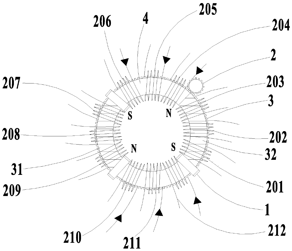
[0031] This embodiment relates to a motor, wherein an exemplary structure such as figure 1 shown. Depend on figure 1 It can be seen that the motor mainly includes two permanent magnets, two magnetically conductive parts 4 and stator coils, but is not limited thereto, multiple permanent magnets, magnetically conductive parts 4 and stator coils can be selected to maintain the stability of the motor when applied to the motor. stability, and can be better applied to different fields.

[0032] Wherein, the rotor is the moving part described in this embodiment, which mainly includes a permanent magnet 31, a permanent magnet 32 ​​and two magnetically conductive parts 4 (equivalent to the stator core), specifically, the permanent magnet and the magnetically conductive part 4 are arranged at intervals and evenly distributed, and the combination is in the shape of a ring; the magnetic conduction part 4 is fixedly connected with the permanent magnet; Relatively; at the same time, the ...

Embodiment 2

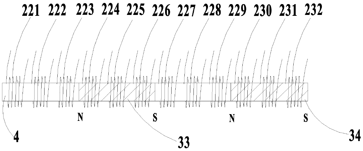
[0048] This embodiment relates to a motor, wherein an exemplary structure such as figure 2 shown. The structure of the motor of this embodiment is similar to that of Embodiment 1, the only difference is that the moving part of this embodiment is a mover, which is composed of two permanent magnets and two magnetic guide parts 4, and the two permanent magnets and two guides The combination of the magnetic parts 4 is linear.

[0049] The stator coils are tightly wound and sleeved on the outside of the mover, and the stator coils can be fixed inside the housing, and are divided into 12 groups. Wherein, the above-mentioned shell is made of magnetically permeable material. Specifically, such as figure 2 As shown, in the illustrated position, the twenty-first stator coil 221, the twenty-second stator coil 222, the twenty-third stator coil 223, the twenty-seventh stator coil 227, the twenty-eighth stator coil 228, the twenty-eighth stator coil 228, The twenty-ninth stator coil 2...


PUM


Abstract

The invention provides a motor which comprises a movement part and a stator coil, wherein the movement part consists of more than one permanent magnets and more than one magnetic conduction parts; thepermanent magnets are uniformly distributed; same magnetic poles of the permanent magnets are opposite; the permanent magnets are axially magnetized; the magnetic conduction parts are arranged in gaps between the adjacent permanent magnets, made of ferromagnetic materials, and fixedly connected with the permanent magnets; the movement part is arranged in a movement part fixing device; the statorcoil is arranged outside the movement part in a sleeving manner, and fixed in a stator coil fixing device; and the stator coil fixing device is made of a magnetic conduction material. According to themotor, the movement part consisting of the magnetic conduction parts and the permanent magnets is designed, the same poles of the permanent magnets are opposite, the stator coil is matched, an interaction force (a magnetic field force and an ampere force) of the stator coil and the movement part wholly acts on a tangential direction, and a torque angle is constant as zero, so that the performanceand the efficiency of the motor are improved.

Description

technical field [0001] The invention relates to the technical field of motors, in particular to a motor. Background technique [0002] A motor is a device that uses an energized coil (that is, a stator winding) to generate a rotating magnetic field and acts on the rotor to form a magnetoelectric force rotation torque, thereby converting electrical energy into mechanical energy. Motors are divided into DC motors and AC motors according to different power sources. At present, motors are widely used in machinery manufacturing industry, metallurgical industry, coal industry, petroleum industry, light textile industry, chemical industry and various other mining enterprises, which play an important role in the development of national economy. [0003] An electric motor usually includes a rotor and a stator, and uses ampere force or magnetic field force to rotate the rotor and output power through an output shaft. There is an included angle between the magnetic field force betwee...

Claims


Application Information

Patent Timeline
Patent Type & Authority Applications(China)
IPC IPC(8): H02K1/27H02K1/14H02K37/14
CPCH02K1/2733H02K1/145H02K37/14
Inventor 张保龙
Owner 张保龙
Learn More