Eureka AIR delivers breakthrough ideas for toughest innovation challenges, trusted by R&D personnel around the world.

Asymmetric half-bridge converter and control method thereof

A half-bridge converter, asymmetrical technology, applied in control/regulation system, DC power input conversion to DC power output, instruments, etc. Consumption and other problems, to achieve the effect of effective control

Active Publication Date: 2019-09-10
MORNSUN GUANGZHOU SCI & TECH
View PDF13 Cites 26 Cited by
  • Summary
  • Abstract
  • Description
  • Claims
  • Application Information

AI Technical Summary

Problems solved by technology

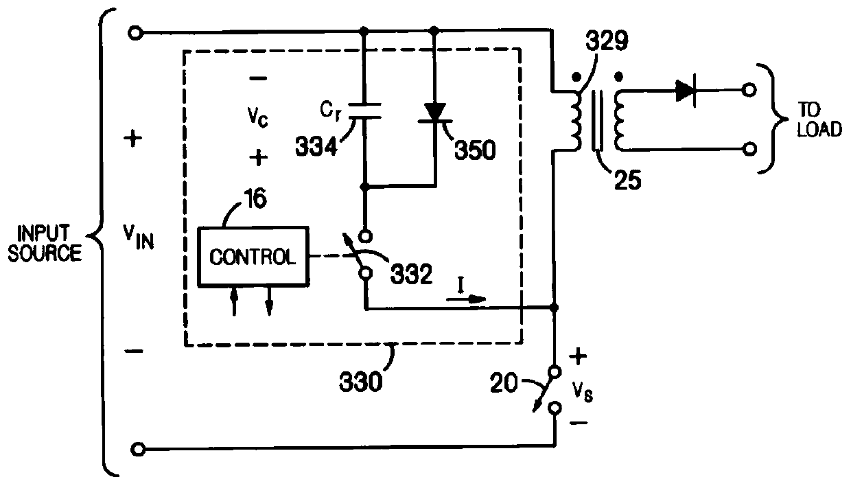
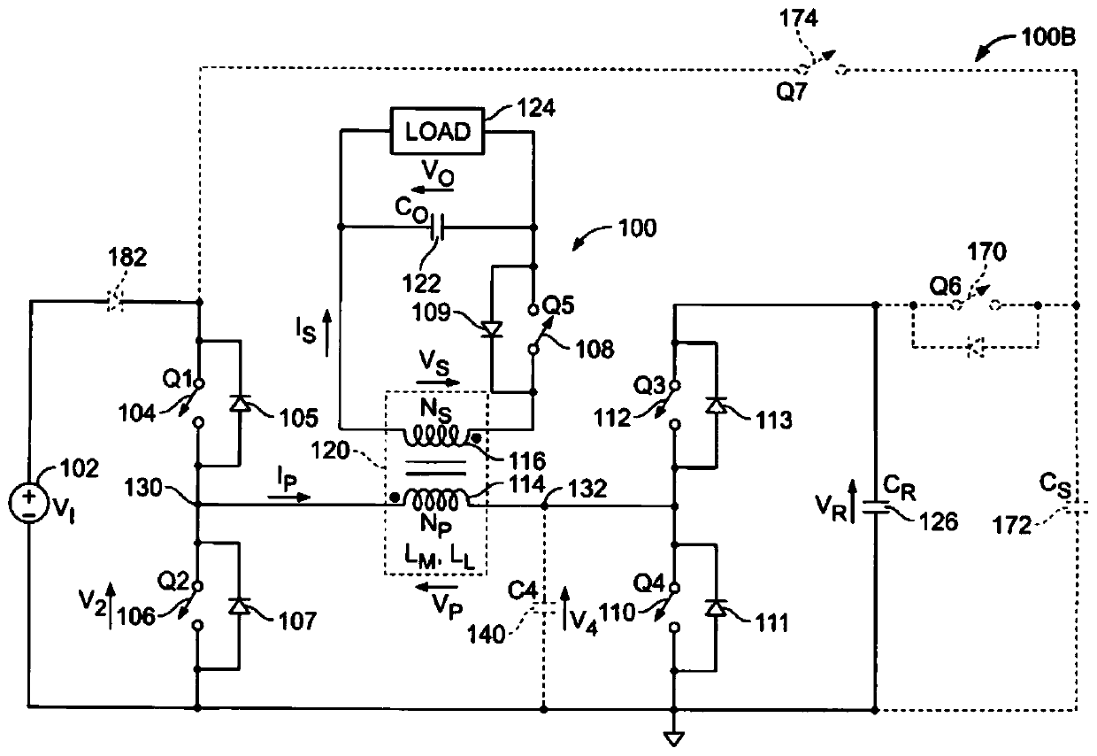
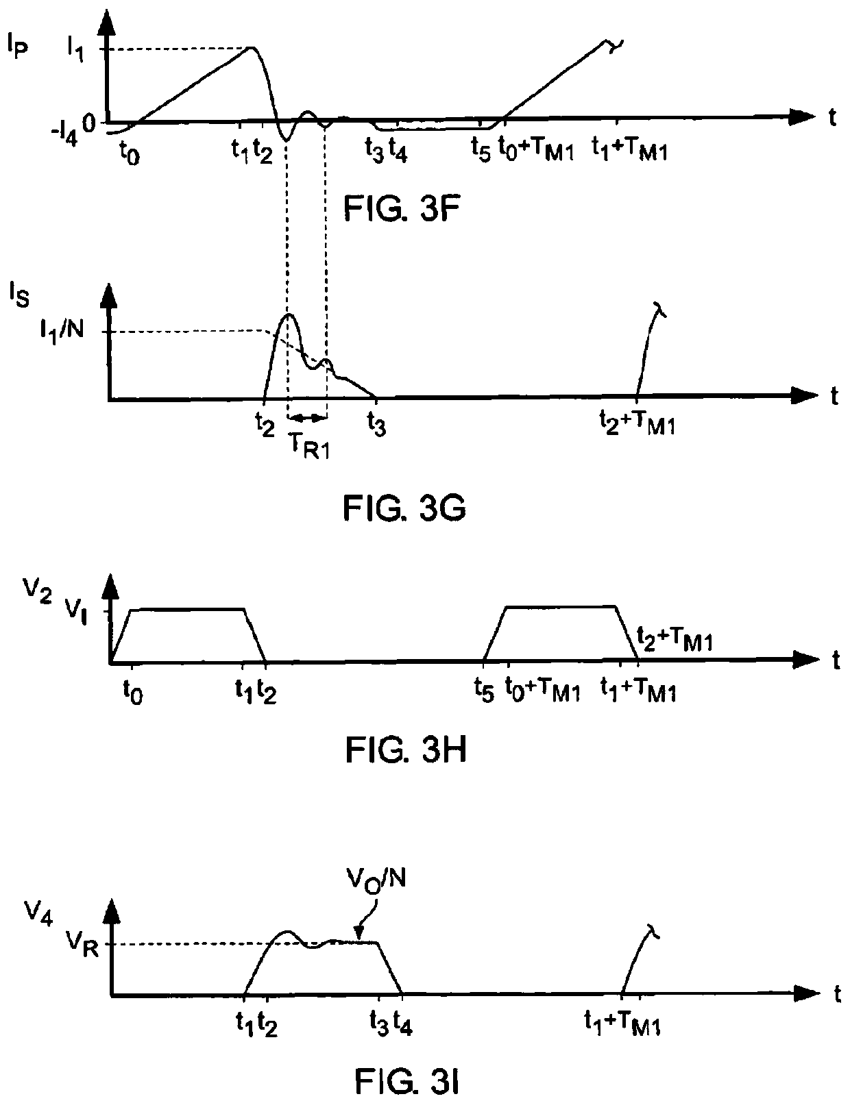
[0025] In view of this, the present invention proposes an asymmetrical half-bridge flyback converter, which can solve the problems of low light load efficiency, large no-load power consumption, and difficulty in taking into account both low-voltage input and high-voltage input in the existing technical solutions. A control method for an asymmetrical half-bridge flyback converter, which is simpler and more efficient in terms of control implementation

Method used


Image

  • Asymmetric half-bridge converter and control method thereof
  • Asymmetric half-bridge converter and control method thereof
  • Asymmetric half-bridge converter and control method thereof

Examples


no. 1 example

[0102] Figure 7 Shown is the circuit diagram of the first embodiment of the present invention, Figure 8 It is a schematic diagram of an equivalent circuit of an asymmetrical half-bridge flyback converter according to the first embodiment of the present invention, Figure 7 and Figure 4 , Figure 8 and Figure 5 The difference is that a unidirectional clamping network Sow is added to the primary side of the transformer, the anode of the unidirectional clamping network Sow is electrically connected to the anode of the primary winding of the transformer, and the cathode of the unidirectional clamping network Sow is connected to the primary side of the transformer Winding cathode electrical connection;

[0103] Figure 9 It is a typical working waveform diagram of the asymmetrical half-bridge flyback converter working in CCM mode according to the first embodiment of the present invention. Each cycle includes five stages: excitation stage, auxiliary switch zero-voltage turn-o...

no. 2 example

[0122] Figure 12 It is a circuit diagram of the second embodiment of the present invention, an asymmetric half-bridge flyback converter. The main difference between the second embodiment of the present invention and the first embodiment lies in the difference in the connection mode of the unidirectional clamping network Sow: the first embodiment Add a unidirectional clamping network Sow to the primary side of the transformer, the anode of the unidirectional clamping network Sow is electrically connected to the anode of the primary winding of the transformer, and the cathode of the unidirectional clamping network Sow is electrically connected to the cathode of the primary winding of the transformer In the second embodiment, a unidirectional clamping network Sow is added on the secondary side of the transformer, the anode of the unidirectional clamping network Sow is electrically connected with the same name end of the transformer secondary winding, and the cathode of the unidir...

no. 3 example

[0125] Figure 13 It is the circuit diagram of the third embodiment of the present invention, an asymmetrical half-bridge flyback converter. The difference from the first embodiment is that the transformer Tr also includes a third winding Np_ow; in the first embodiment, the primary side of the transformer is increased A unidirectional clamping network Sow, the anode of the unidirectional clamping network Sow is electrically connected with the anode of the primary winding of the transformer, and the cathode of the unidirectional clamping network Sow is electrically connected with the negative electrode of the primary winding of the transformer; in the third embodiment A unidirectional clamping network Sow is added to the third winding Np_ow of the transformer, the anode of the unidirectional clamping network Sow is electrically connected to the terminal with the same name of the third winding Np_ow, and the cathode of the unidirectional clamping network Sow is electrically conne...


PUM


Abstract

The invention discloses an asymmetric half-bridge converter and a control method thereof. A one-way clamping network is additionally arranged and is connected in parallel with a primary side, a secondary side or a third winding of a transformer, an auxiliary switch is controlled to be switched off when an excitation inductance current reaches a set value, the one-way clamping network is conducted,a clamping current passes through the one-way clamping network, the clamping current is clamped and maintained to be basically unchanged by the one-way clamping network, the one-way clamping networkis controlled to be switched off within a certain time before a main switch is conducted, the clamping current is released, voltages of two ends of the main switch are reduced to zero or be approximate to zero, and zero-voltage conduction of the main switch is achieved. By the asymmetric half-bridge converter, effective control of negative peak of the excitation inductance current can be achieved,a current effective value of a power device under light load of a converter is reduced, the light-load efficiency of the converter is substantially reduced under the condition that the advantages ofzero-voltage conduction of an existing technical scheme is maintained, the no-load loss is reduced, and control implementation is simple and efficient.

Description

technical field [0001] The invention relates to a switching converter, in particular to an asymmetrical half-bridge converter and a control method thereof. Background technique [0002] The switching converters that have been developed and applied since the 1960s mostly use hard switching technology. However, with the development of science and technology, all walks of life have put forward higher requirements for power supplies, and high efficiency, high power density, and miniaturization have become the main topics of research in the power supply industry. Switching converters using hard switching technology have disadvantages such as large switching loss, low efficiency, low switching frequency, and poor EMI. For this reason, soft switching technology has emerged. The so-called soft switching refers to: Zero-Voltage-Switching (Zero-Voltage-Switching) , referred to as ZVS; zero current switching (Zero-Current-Switching), referred to as ZCS. Soft switching technology main...

Claims


Application Information

Patent Timeline
IPC IPC(8): H02M3/335
CPCH02M3/33569H02M1/0058Y02B70/10
Inventor 任鹏程杜波王志燊李璐
Owner MORNSUN GUANGZHOU SCI & TECH
Why Eureka
Eureka Blog
Learn More