Construction method of high-speed railway overhead line support column foundation structure

A basic structure and construction method technology, applied in basic structure engineering, construction and other directions, can solve the problems of no proposed construction method, large environmental pollution and large impact of excavation, and achieve easy popularization and use, convenient and efficient construction, and foundation pit excavation. less digging effect

Active Publication Date: 2019-09-13
CHINA RAILWAY ERYUAN ENG GRP CO LTD
View PDF5 Cites 0 Cited by
  • Summary
  • Abstract
  • Description
  • Claims
  • Application Information

AI Technical Summary

Problems solved by technology

[0003] (1) It is difficult and inefficient to excavate a small-diameter foundation pit with a depth of 2-3m after subgrade filling;
[0004] (2) The excavation of the foundation pit affects the compactness of the filled subgrade, and has a greater impact on the high-speed railway;
[0005] (3) When the filling roadbed is provided with a waterproof and drainage geotechnical material layer, the excavation will easily damage the waterproof and drainage geotechnical material, which will affect the waterproof and drainage effect of the roadbed;
[0006] (4) Excavation and filling of foundation pits, resulting in waste of materials and great environmental pollution during excavation
[0009] The above-mentioned utility model patents all have certain restrictions on use conditions, and no suitable construction method has been proposed. Therefore, further improvements are needed to propose a contactor that is suitable for all filling subgrades, convenient and efficient construction, and less excavation of foundation pits. The construction method of net pillar foundation is of great significance

Method used


Image

  • Construction method of high-speed railway overhead line support column foundation structure

Examples


Embodiment Construction

[0029] The present invention will be further explained below in conjunction with the drawings and embodiments:

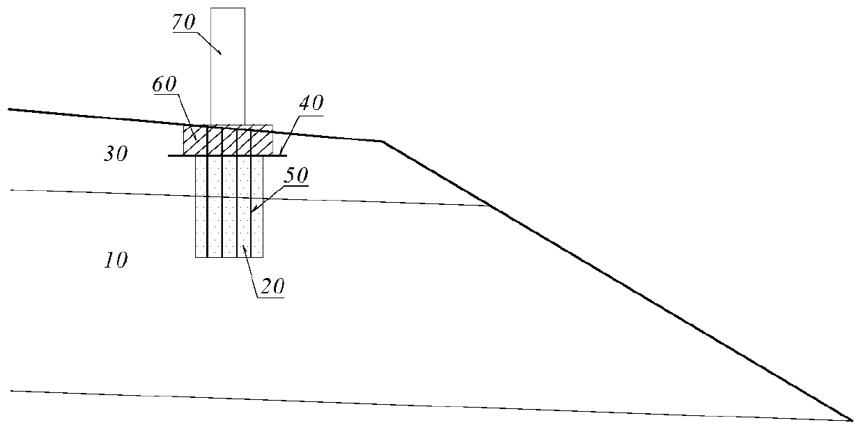
[0030] Reference figure 1 , The construction method of a high-speed railway catenary pillar foundation structure provided by the present invention includes the following steps:

[0031] ① Fill the lower part of the subgrade 10 in layers to the elevation position of the bottom of the catenary pillar foundation;

[0032] ②Continue to fill up the subgrade subgrade 10 and subgrade surface structure 30 above the bottom elevation of the catenary pillar foundation in layers, and fill the corresponding position of the catenary pillar foundation with water-permeable filler to form the water-permeable filler material 20 until the subgrade surface structure 30 20-30cm below the top surface;

[0033] ③Lay a layer of composite geomembrane 40 on the top of the water-permeable filling material 20, the size of the composite geomembrane 40 is larger than that of the contact net pillar foun...


PUM


Abstract

The invention relates to a construction method of a high-speed railway overhead line support column foundation structure. The construction method of the high-speed railway overhead line support columnfoundation structure is suitable for construction of all types of filling roadbed, and the construction is convenient and efficient. The construction method includes the following steps that 1, a roadbed lower filling body is subjected to filling in a layered mode to the bottom elevation of an overhead line support column foundation; 2, the roadbed lower filling body and a roadbed surface structure continue to be subjected to layering filling, and water seepage filler is adopted at a corresponding position of the overhead line support column foundation for filling to form a seepage filler filling body; 3, a layer of composite geomembrane is laid at top of the seepage filler filling body; 4, the remaining roadbed surface structure is filled; 5, self-drilling type anchor bolts are constructed at intervals in the seepage water filler filling body; 6, pressure grouting is performed on the self-drilling type anchor bolts to form a high-strength reinforced composite cement mortar body; 7, the roadbed surface structure above the top surface of the high-strength reinforced composite cement mortar body is removed by excavation; 8, steel cages are bound in a shallow foundation pit, and arefixedly connected with the top of each of the exposed self-drilling type anchor bolts; and 9, concrete is poured in the shallow foundation pit to form a reinforced concrete base.

Description

Technical field [0001] The invention relates to railway engineering, in particular to a construction method of a high-speed railway catenary pillar foundation structure. Background technique [0002] The catenary pillar foundation set on the railway subgrade is usually after the subgrade filling is completed, the foundation pit of the catenary pillar foundation is excavated by a rotary drilling machine or manual digging, and then reinforced concrete is poured into the foundation pit. This construction method has the following problems: [0003] (1) Excavation of a 2-3m deep small-diameter foundation pit after the roadbed is filled is difficult and low in efficiency; [0004] (2) Excavation of foundation pits affects the compactness of the filled roadbed, and has a greater impact on high-speed railways; [0005] (3) When the filled roadbed is equipped with a waterproof and drainage geotechnical material layer, the excavation is very easy to damage the waterproof and drainage geotechni...

Claims


Application Information

Patent Timeline
Patent Type & Authority Applications(China)
IPC IPC(8): E02D27/42
CPCE02D27/42
Inventor 姚裕春谢毅张耀韦耀琥封志军肖朝乾周波袁报
Owner CHINA RAILWAY ERYUAN ENG GRP CO LTD
Why Eureka
Try Eureka