Push-condensing integrated high-resolution space optical load ultra-light carbon fiber truss support structure

A space optics and support structure technology, applied in optics, optical components, installation, etc., can solve the problems of poor structural strength, rigidity index, difficult grinding, difficult fine-tuning, etc., and achieve simple processing technology, simple assembly process, and guaranteed position relationship effect

Active Publication Date: 2019-09-13
CHANGCHUN INST OF OPTICS FINE MECHANICS & PHYSICS CHINESE ACAD OF SCI
View PDF4 Cites 11 Cited by
  • Summary
  • Abstract
  • Description
  • Claims
  • Application Information

AI Technical Summary

Problems solved by technology

The main disadvantages of this structure are: ①The mass is 6.07kg, the first-order fundamental frequency is 138Hz lower, and the structural strength and stiffness index is poor; The lower ring of the truss) is connected together, resulting in excessively large axial dimensions and heavy weight of the support structure. After the truss assembly is assembled, it is not easy to grind the two end faces of the support structure, resulting in poor parallelism between the two ends of the plane and the two ends of the plane. The verticality difference of the truss axis affects the installation accuracy of the camera’s primary and secondary mirrors and the relative position between the primary and secondary mirrors; The position between the mirrors is fine-tuned; ④The mounting holes for the camera hood are not given around the secondary mirror chamber

Method used


Image

  • Push-condensing integrated high-resolution space optical load ultra-light carbon fiber truss support structure
  • Push-condensing integrated high-resolution space optical load ultra-light carbon fiber truss support structure
  • Push-condensing integrated high-resolution space optical load ultra-light carbon fiber truss support structure

Examples


Embodiment Construction

[0035] The present invention will be described in detail below in conjunction with the accompanying drawings.

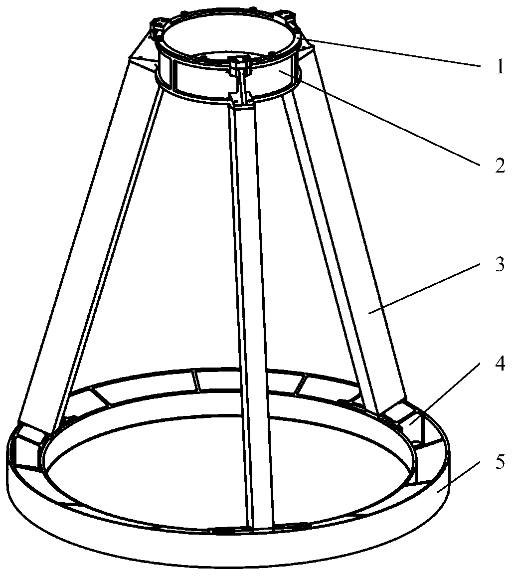
[0036] The ultra-light carbon fiber truss support structure of the push-condensation integrated high-resolution space optical load of the present invention is as follows: figure 1 As shown, it includes an adjusting gasket 1, a secondary mirror chamber 2, a truss rod 3, a metal embedded part 4, and a support ring 5.

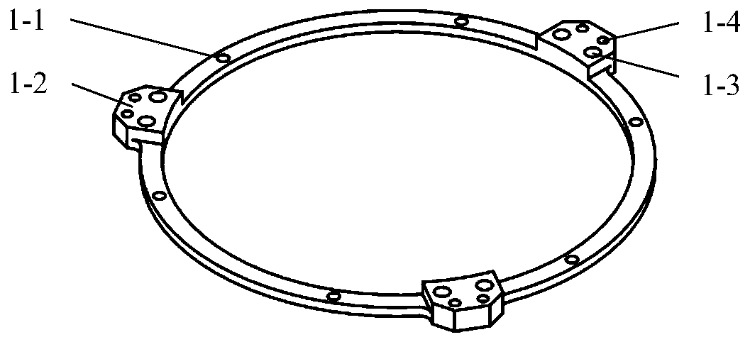
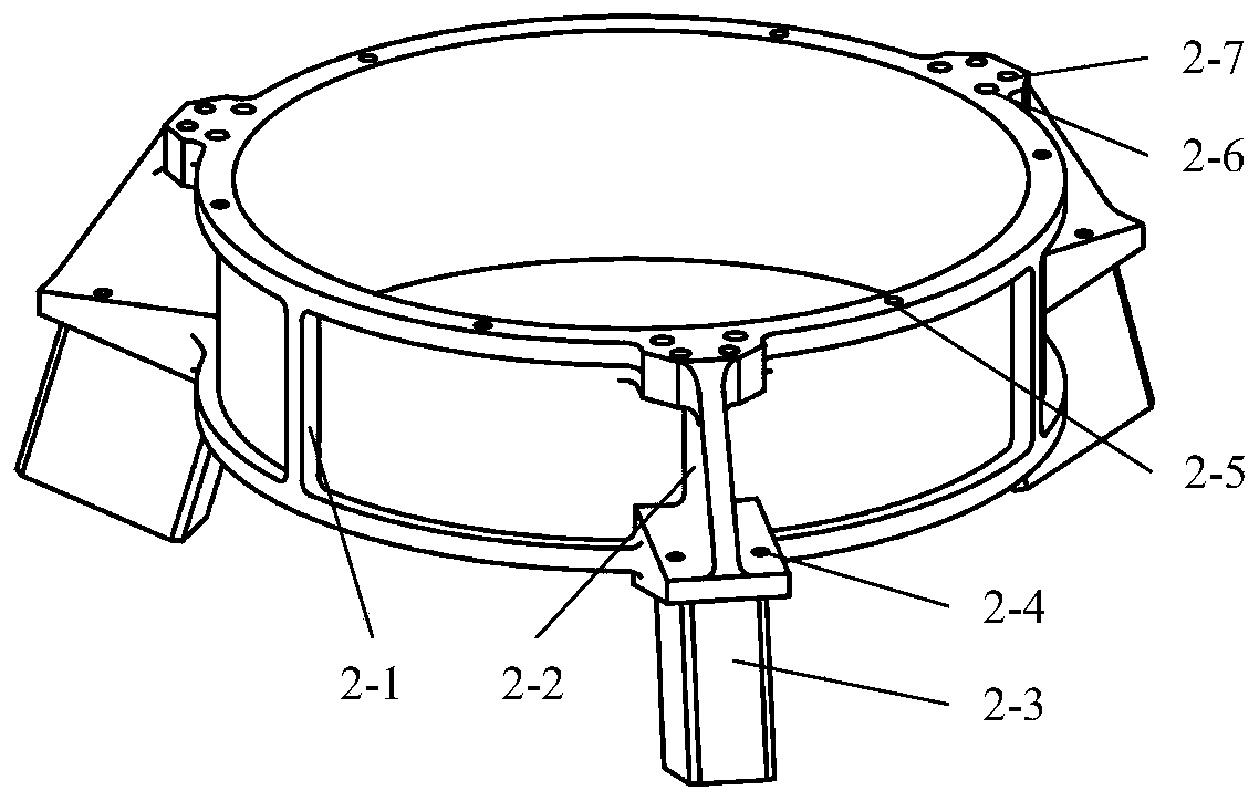
[0037] The adjusting gasket 1 is made of titanium alloy material, such as figure 2 As shown, 6 first screw through holes 1-1 are evenly distributed on the circumference, and 6 second threaded holes 2-5 are evenly distributed on the corresponding positions on the upper end surface of the secondary mirror chamber 2, as Figure 3aAs shown, the adjusting gasket 1 is connected with the secondary mirror chamber 2 by screws. Three first bosses 1-2 are evenly distributed on the upper end of the adjustment spacer 1, which is the installation plane of the secon...


PUM


Abstract

The invention relates to a push-condensing integrated high-resolution space optical load ultra-light carbon fiber truss support structure. The structure comprises an adjusting gasket, a secondary lenschamber, a truss rod, a metal embedded part and a support ring. A boss at the upper end of the adjusting gasket is an installation plane of a secondary mirror component, and a boss at the lower end of the metal embedded part is an installation plane of a truss and a primary mirror component. The adjusting gasket, the secondary lens chamber and the metal embedded part are made of titanium alloy materials, and the truss rod and the support ring are made of carbon fiber composite materials. The cross section of the truss rod is concentric-square-shaped, and the cross section of the support ringis concave-shaped. The truss support structure is less than 2.2 kg in total mass and is 1/3-1/2 times of the mass of a traditional metal truss. The truss support structure is simple, light in weight,good in strength, rigidity, structural stability and other index characteristics, can resist the influence of a complex mechanical environment on a space optical load in the transmitting process, ensures the position relation among optical elements, and meets the requirement of the push-condensing integrated high-resolution space optical load on the support structure.

Description

technical field [0001] The invention belongs to the technical field of space optics and precision machinery, and in particular relates to an ultra-light carbon fiber truss support structure with push-condensation integration and high-resolution space optical load. Background technique [0002] The carbon fiber truss for space optical load is the supporting structure between the main optical components. It must have good strength, stiffness and structural stability to resist the influence of the complex mechanical environment of the optical load during launch and ensure that the optical components The positional relationship ensures the imaging quality of the optical load. Compared with traditional metal materials, carbon fiber composite materials have physical and mechanical properties such as low density, high specific strength, high specific stiffness, and good thermal stability. At the same time, the preparation process of carbon fiber composite structural parts is becomi...

Claims


Application Information

Patent Timeline
Patent Type & Authority Applications(China)
IPC IPC(8): G02B7/00
CPCG02B7/00
Inventor 解鹏王凯金光刘春雨徐明林
Owner CHANGCHUN INST OF OPTICS FINE MECHANICS & PHYSICS CHINESE ACAD OF SCI
Why Eureka
Try Eureka