PCB board of planar transformer and preparation method thereof

A planar transformer, PCB board technology, applied in the direction of transformer/inductor parts, inductor/transformer/magnet manufacturing, transformer/inductor magnetic core, etc., can solve the problem of low winding efficiency of multi-layer superimposed winding and complicated PCB board process and other problems to achieve the effect of reducing the time for coating the self-adhesive layer, product qualification rate and product consistency guarantee, and cost reduction

Pending Publication Date: 2019-09-13
SHENZHEN SUNLORD ELECTRONICS
View PDF0 Cites 5 Cited by
  • Summary
  • Abstract
  • Description
  • Claims
  • Application Information

AI Technical Summary

Problems solved by technology

[0004] The main purpose of the present invention is to propose a PCB board with a colloid injection integrally formed double-sided winding part and can be automatically and simultaneously double-sidedly wound by automatic winding equipment and its manufacturing method to solve the problem of PCB board technology in the application of planar transformers. Complexity and low winding efficiency of multi-layer stacked windings

Method used


Image

  • PCB board of planar transformer and preparation method thereof
  • PCB board of planar transformer and preparation method thereof
  • PCB board of planar transformer and preparation method thereof

Examples


Embodiment Construction

[0025] The present invention will be further described below in conjunction with the accompanying drawings and specific embodiments.

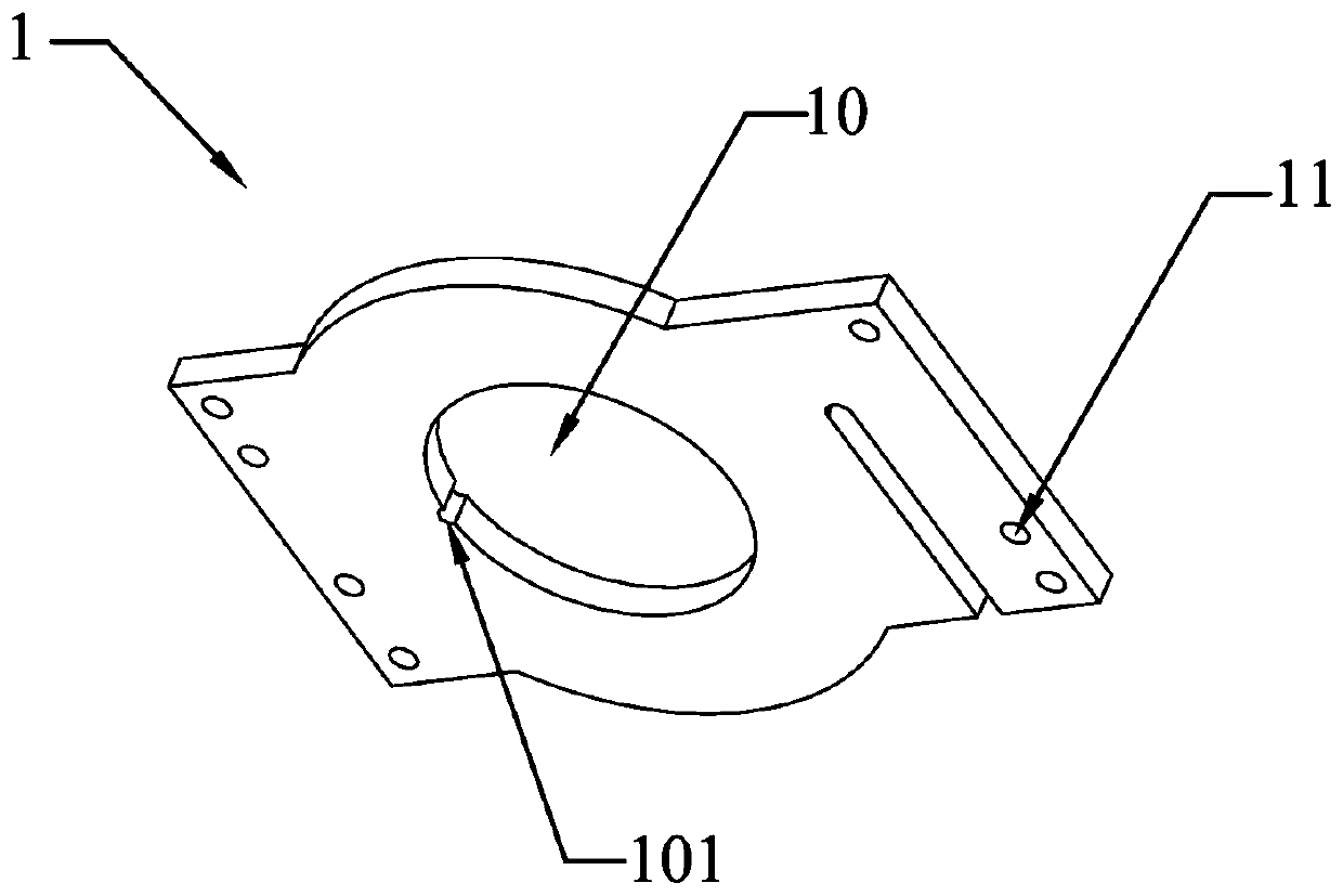
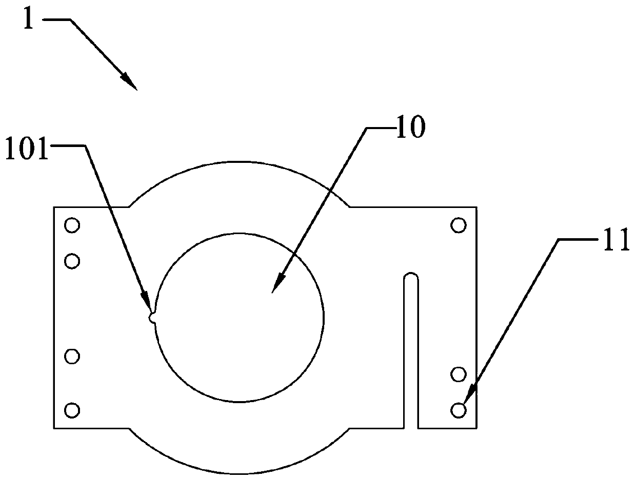
[0026] The specific embodiment of the present invention proposes a PCB board of a planar transformer, and the planar transformer is mainly applied to a mobile phone fast charging source adapter, and can also be used on a tablet computer and a new energy vehicle power adapter; and the present invention proposes The above-mentioned PCB board does not need to be coated with a self-adhesive layer on the surface, but forms an integrated double-sided winding part on the PCB substrate by colloid injection molding for double-sided plane winding, thereby eliminating the need for self-adhesive coating. The labor cost caused by the self-adhesive layer and a series of problems caused by avoiding the secondary heating of the self-adhesive layer.

[0027] refer to Figure 1 to Figure 7 , the planar transformer PCB board proposed by the specific embodiment o...


PUM


Abstract

The present invention discloses a PCB board of a planar transformer and a preparation method thereof. Both surfaces of a PCB substrate with a through hole are subjected to colloid injection molding, and a double-surface wire-winding part integrated with the PCB substrate is formed. The two surfaces, on the PCB substrate, of the double-surface wire-winding part are symmetrical structures, the center of the double-surface wire-winding part is a via hole identical with the through hole, and the via hole is aligned with the through hole to form a magnetic core hole used for allowing a magnetic core to pass through. The periphery of the via hole is bulged to form a wire-blocking part. The hole wall of the magnetic core hole is provided with a wire-passing slot used for allowing one metal wire to pass through, so that the two surfaces of the double-surface wire-winding part are subjected to planar wire-winding from inside to outside at the same time, and thus two series-connected coils, located on both surfaces of the PCB substrate, are formed. According to the PCB board, the coating of a self-adhesive layer on both surfaces of the PCB substrate is unnecessary, and thus the time of coating the self-adhesive layer is reduced; and a series of problems, for example, the adhered self-adhesive layer gathers in a wire-winding process caused by the flowing phenomenon of the self-adhesive layer in a baking process, are solved.

Description

technical field [0001] The invention relates to a PCB board of a planar transformer and a manufacturing method thereof. Background technique [0002] Generally, the traditional transformer is a wire-wound transformer, which is assembled by winding the coil on the skeleton and using a magnetic core or directly winding on the magnetic ring. This type of product has complex structure and large product volume; low cost reduction ability; large equipment cost investment, high difficulty in model change; product consistency, poor stability, high potential failure risk, etc.; for small internal space, energy saving and heat dissipation requirements Harsh and in national defense, aviation, aerospace and other fields that require high weight and stability, planar transformers are now gradually playing a greater role, but planar transformers also have major shortcomings. For multi-layer stacked windings, PCB board technology Complicated and expensive. [0003] The disclosure of the ...

Claims


Application Information

Patent Timeline
Patent Type & Authority Applications(China)
IPC IPC(8): H01F27/28H01F41/04H01F41/074
CPCH01F27/2804H01F27/2823H01F27/2871H01F41/041H01F41/074H01F2027/2819H01F27/325H01F27/306H05K3/0014H05K2201/10287H05K2201/1003H05K3/32H05K2201/09118H05K2201/09063H05K2201/086H01F27/2828H01F41/061H01F41/10H01F27/24H01F41/0206H05K1/0213
Inventor 查小月欧阳过任菁菁
Owner SHENZHEN SUNLORD ELECTRONICS
Why Eureka
Try Eureka