
Tapered semiconductor laser based on annular outer cavity

A laser and semiconductor technology, applied in semiconductor lasers, lasers, phonon exciters, etc., can solve the problems of narrow spectral tuning range, low spatial brightness, low back-end coupling efficiency, etc., and achieve high diffraction efficiency, large angle change, Effect of High Efficiency Tuning

Active Publication Date: 2019-09-13
INST OF APPLIED ELECTRONICS CHINA ACAD OF ENG PHYSICS
View PDF6 Cites 2 Cited by
  • Summary
  • Abstract
  • Description
  • Claims
  • Application Information

AI Technical Summary

Problems solved by technology

However, there are two problems when it is applied to a tapered laser: First, due to the special structure of the tapered DL, the length and width of the ridge waveguide are generally only 1 μm×(3-5) μm, and the reflected light is injected back into the front cavity surface from the external cavity grating. Excessive backpropagation power density may cause burnout at the junction of the cone-ridge waveguide or the rear cavity surface
Second, in addition to being coupled back to the ridge waveguide, part of the reflected light forms multi-mode oscillations between the front and rear cavity surfaces. This part of multi-mode light may damage the beam quality of the cone laser
Although the above methods can narrow the spectral width or achieve spectral tuning to a certain extent, these methods have the defects of low spatial brightness, narrow spectral tuning range, and low back-end coupling efficiency to varying degrees.

Method used


Image

  • Tapered semiconductor laser based on annular outer cavity
  • Tapered semiconductor laser based on annular outer cavity
  • Tapered semiconductor laser based on annular outer cavity

Examples


Embodiment Construction

[0034] All features disclosed in this specification, or steps in all methods or processes disclosed, may be combined in any manner, except for mutually exclusive features and / or steps.

[0035] Any feature disclosed in this specification, unless specifically stated, can be replaced by other alternative features that are equivalent or have similar purposes. That is, unless expressly stated otherwise, each feature is one example only of a series of equivalent or similar features.

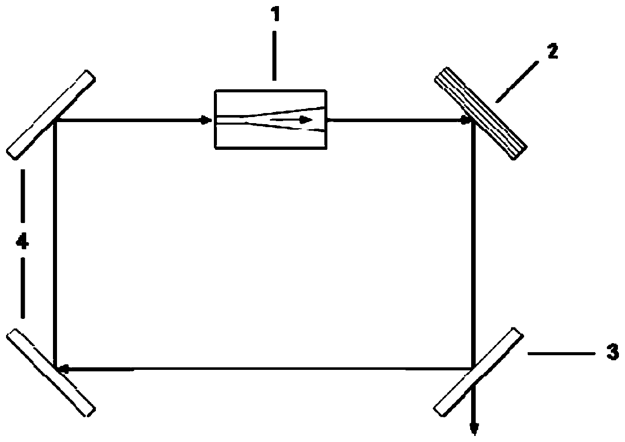
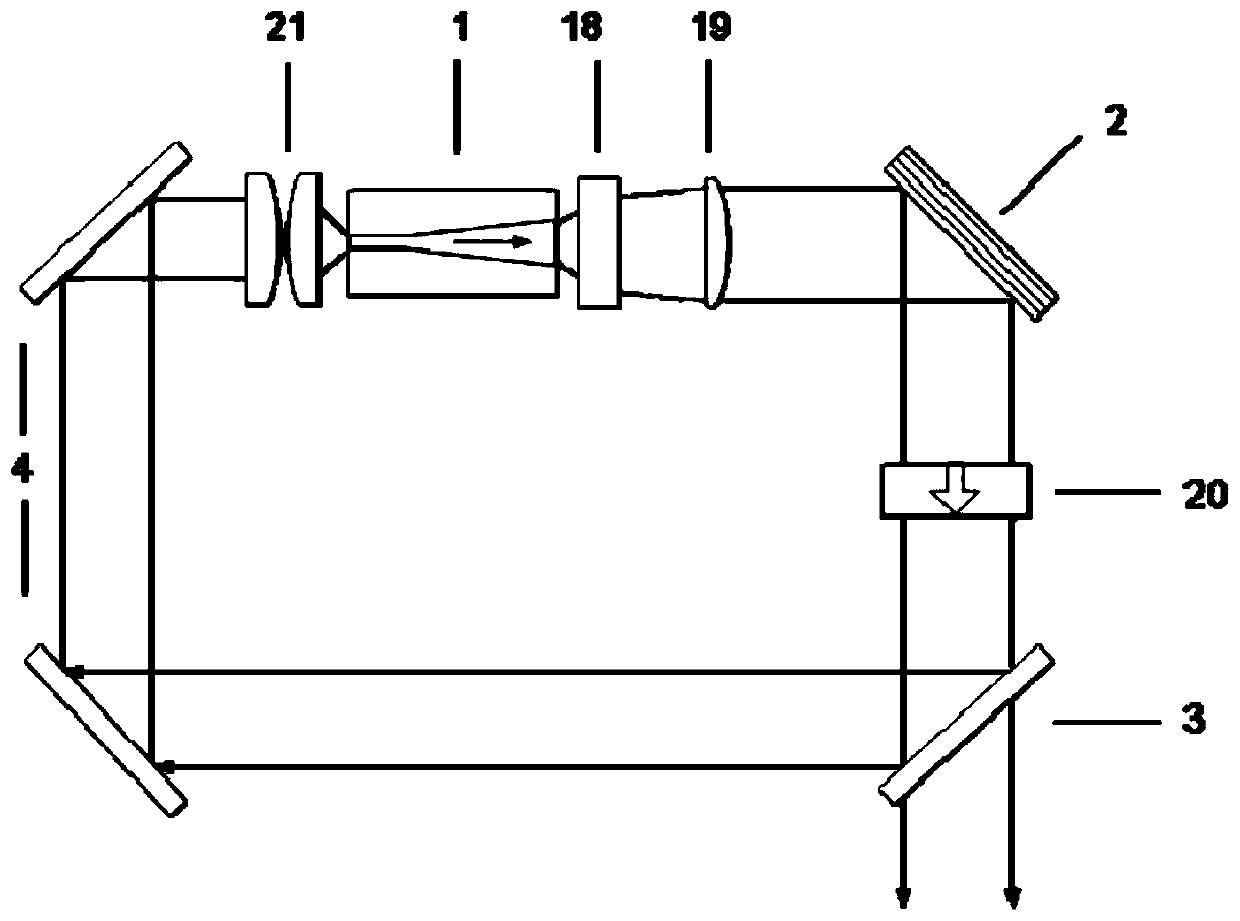
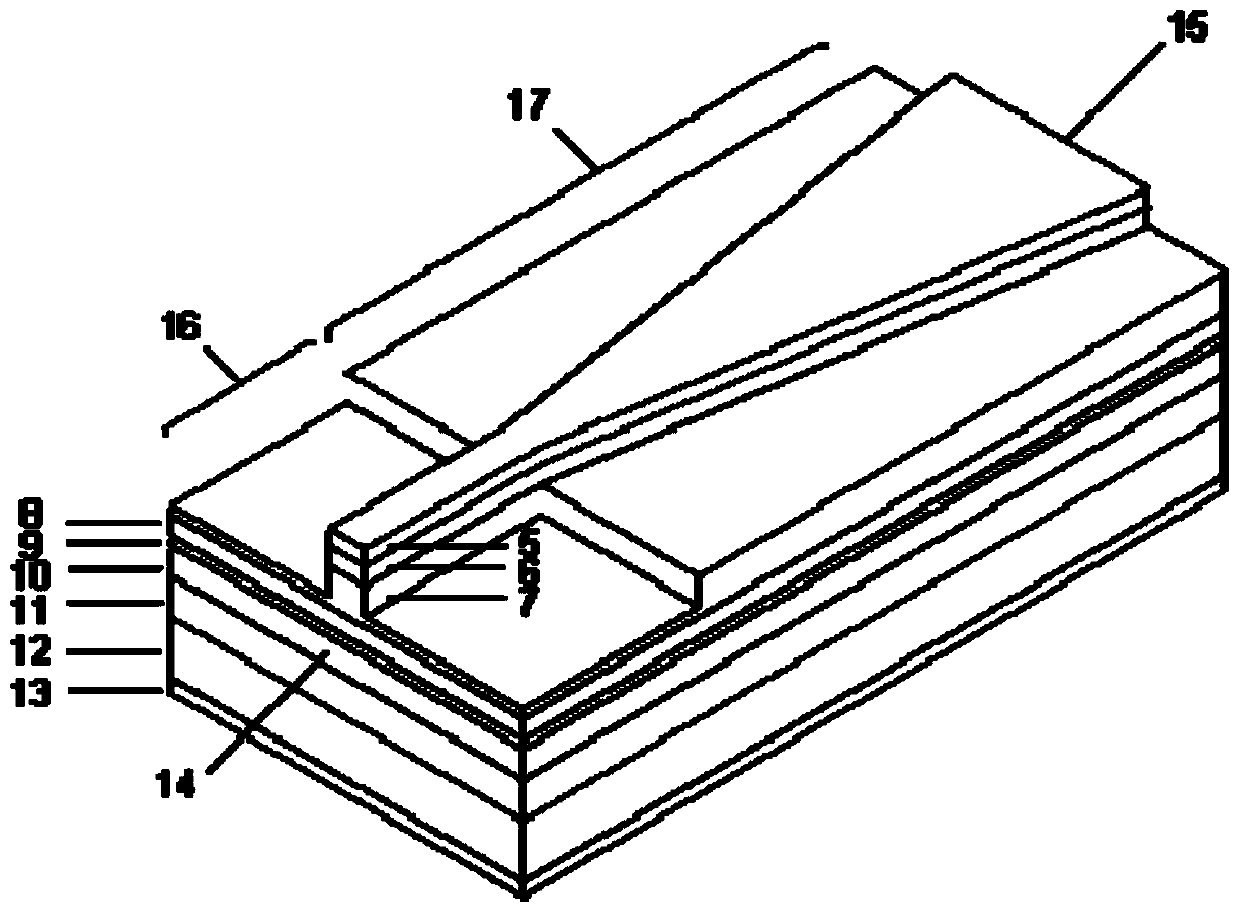
[0036] like Figure 1-3 As shown, a kind of tapered semiconductor laser based on the annular external cavity of the present embodiment includes a tapered laser 1, a diffraction grating 2, a beam splitter 3 and a total reflection mirror group 4; the total reflection mirror group 4 includes two total reflection mirrors mirror;

[0037] The tapered laser 1 includes a front cavity surface 15, a rear cavity surface 14, a ridge waveguide region 16 and a tapered gain amplification region 17;

[0038] The ...


PUM


Abstract

The invention discloses a tapered semiconductor laser based on an annular outer cavity. The tapered semiconductor laser comprises a tapered laser, a diffraction grating, a beam splitter and a total reflection mirror group. The tapered laser comprises a front cavity surface, a rear cavity surface, a ridge waveguide region and a tapered gain amplification region; the diffraction grating is positioned in the light emitting direction of the tapered laser; the beam splitter is positioned in the diffraction light direction of the diffraction grating; the total reflection mirror group transmits lightreflected by the beam splitter to the rear cavity surface of the tapered laser in a steering mode, the tapered laser emits a laser from the front cavity surface to enter the diffraction grating, thelaser is transmitted to the beam splitter for light splitting through diffraction of the diffraction grating, most of the light is directly output, small part of the light is transmitted to the rear cavity surface of the tapered laser in a steering mode through the total reflection mirror group after being reflected, and the light is subjected to power amplification through a reference-selection transverse mode and the tapered gain amplification region of a ridge waveguide region and then is emitted to form circulation. The tapered semiconductor laser based on the annular outer cavity can generate the tunable high-brightness laser with the narrow spectral width while keeping the high light beam quality of the tapered semiconductor laser based on the annular outer cavity.

Description

technical field [0001] The invention relates to a tapered semiconductor laser based on an annular external cavity, belonging to the technical field of semiconductor lasers. Background technique [0002] High-brightness semiconductor laser is a research hotspot in the field of solid-state laser, which has the characteristics of high laser power and good beam quality. The generalized high brightness includes high spatial brightness and hyperspectral brightness. High spatial brightness semiconductor lasers have a variety of structure types, among which the most promising one is the cone-shaped semiconductor laser based on the ring-shaped external cavity (referred to as the cone-shaped laser), which combines the single-mode high-beam quality ridge-shaped main oscillation region with the cone-shaped The gain amplification section is integrated in the same device, thus providing high output power while still maintaining good beam quality. The monolithic semiconductor laser with ...

Claims


Application Information

Patent Timeline
IPC IPC(8): H01S5/14
CPCH01S5/141
Inventor 李弋唐淳周坤杜维川高松信武德勇胡耀张亮
Owner INST OF APPLIED ELECTRONICS CHINA ACAD OF ENG PHYSICS
Learn More