
Card clothings, flat strips with clothing and machines with flat strips

A technology of card clothing and machine, applied in the field of card clothing, can solve the problems of high cost, increase cost, time-consuming, etc., and achieve the effect of maintaining structure, simplifying assembly, and reliable electrical contact

Active Publication Date: 2022-02-01
TRUETZSCHLER GRP SE
View PDF8 Cites 0 Cited by
  • Summary
  • Abstract
  • Description
  • Claims
  • Application Information

AI Technical Summary

Problems solved by technology

This is time consuming and requires new sensors to be prepared each time, which is costly
Moreover, such sensors are required in each component to be monitored, which again raises the cost

Method used


Image

  • Card clothings, flat strips with clothing and machines with flat strips
  • Card clothings, flat strips with clothing and machines with flat strips
  • Card clothings, flat strips with clothing and machines with flat strips

Examples


no. 1 approach

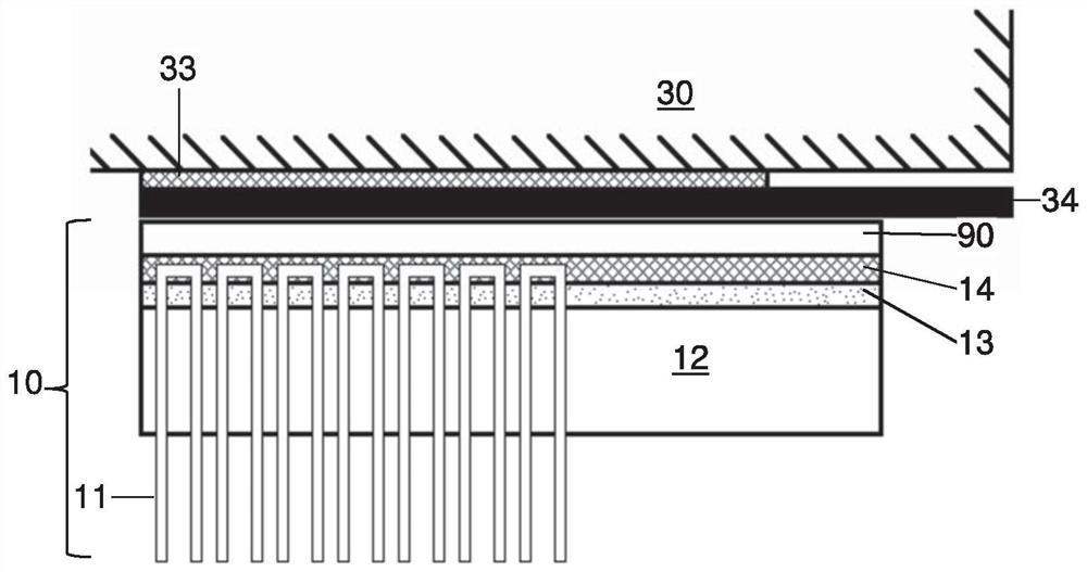
[0045] figure 1 An arrangement with a carrier 30 and a card wire 10 is shown, which is constructed according to the first embodiment of the invention.

[0046] The bracket 30 includes an adhesive layer 33 on which a magnetic strip 34 is mounted. On the side of the card clothing 10 facing the carrier 30 there is a backing plate 90 which consists of a magnetizable material, such as steel. The card clothing 10 is mounted or held on the support 30 via said back plate 90 .

[0047] On the side facing away from the carrier 30 , the backplane 90 is attached to the electrically conductive layer 13 by means of the intermediate layer 14 , here designed as an adhesive layer. On the side of the electrically conductive layer 13 facing away from the support 30 , the base 12 of the clothing 10 is now fastened, which base can consist, for example, of a plurality of layers or of fabric layers glued together. Base 12 is typically constructed from five layers of cotton fabric. Since the base...


PUM

PropertyMeasurementUnit
electrical resistanceaaaaaaaaaa

Abstract

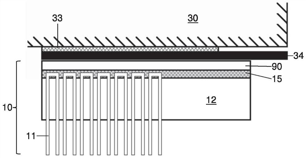
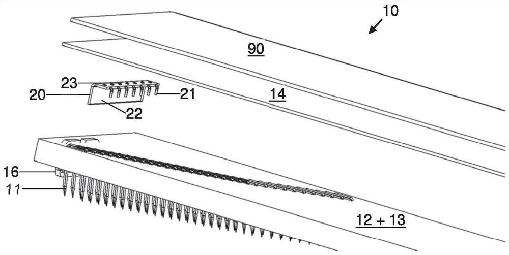
The card wire (10) has a base (12), a card wire passing through the base, held in place by the base and protruding on a first side of the base (12) The needle (11) and the electrically conductive layer (13, 15) are arranged on the second side of the base (12) facing away from the first side, so that the layer is in contact with the clothing needle (11) in the Electrical contacts are made on the second side of the base (12). Alternatively the layer (15) is an integral part of the base (12) and the needles (11) pass through the layer in contact with the layer (15). The layer (15) has a textile fabric (15) with electrically conductive threads which are electrically coupled to each other directly or indirectly via the clothing needles (11), which extend along or transversely to the clothing (10), said The card clothing has electrically conductive contact elements (20), so that they are in electrical contact with the layers (13, 15), so that the contact sections are electrically coupled to all wires. The contact element (20) has a connection section (16), which is designed for electrical contact with an external element (50). The flat strips (10, 20, 30) have a clothing carrier (30) comprising a holding section and an electrically conductive clothing-connecting section (20) forming the outer element (50) and in said clothing carrier ( 30) Card clothing (10) held in a fixed position. The spinning preparation machine has such a flat strip (10, 20, 30), a flat strip support (70) for holding the flat strip (10, 20, 30) and a flat strip-contact section (3) , which is designed to be electrically coupled to the clothing-connecting section (20) when the flat strips (10, 20, 30) are mounted on the flat strip holder (70).

Description

technical field [0001] The invention relates to a card clothing, a clothing carrier provided therefor and a spinning preparation machine, such as a card, equipped with these. Background technique [0002] Such card clothings are known. The clothing mainly comprises a base through which the clothing needles, which are U-shaped in cross-section and groove-shaped, pass through the base. The free ends of the clothing needles protrude from the base from the respective side of the base and interact with a clothing provided eg on a cylinder. Due to the very small distance between the two clothings (for example 0.2 mm), the needles of these clothings come into mechanical contact with each other due to thermal deformations, eg due to operation or ambient temperature. This leads to excessive mechanical loading of the individual clothings and possible damage. [0003] To overcome said problems, different solutions have been developed in order to detect the mutual contact of two inte...

Claims


Application Information

Patent Timeline
Patent Type & Authority Patents(China)
IPC IPC(8): D01G15/86
CPCD01G15/86
Inventor 安德烈亚斯·泽博德卡克里斯托夫·莱德斯迪特玛·弗洛克罗伯特·皮其尔
Owner TRUETZSCHLER GRP SE
Learn More