
Aqueous humor collection device

A collection device and aqueous humor technology, applied in the field of medical devices, can solve the problems of aqueous humor waste, difficulty in controlling the drainage speed of aqueous humor, poor safety and reliability, etc., so as to avoid leakage of aqueous humor, avoid sudden drop of intraocular pressure, improve The effect of accuracy

Active Publication Date: 2020-06-30
BEIJING SIGHTNOVO MEDICAL TECH CO LTD
View PDF10 Cites 0 Cited by
  • Summary
  • Abstract
  • Description
  • Claims
  • Application Information

AI Technical Summary

Problems solved by technology

However, in the process of puncturing with the 1ml syringe needle, the drainage speed of aqueous humor is difficult to control. When the liquid is drained too quickly, it will cause a rapid drop in intraocular pressure, and even cause other complications in severe cases.
In addition, since the aqueous humor in the syringe cavity needs to be further transferred to the microcentrifuge tube after the aqueous humor collection is completed, the aqueous humor will be wasted during the process, and the aqueous humor may be mixed with the external environment during the transfer process. The risk of contamination due to contact, resulting in biased test results and poor reliability
[0004] It can be seen that at this stage, it is urgent to develop a new type of acquisition device that can solve the problems of poor safety and reliability in the anterior chamber puncture process.

Method used


Image

  • Aqueous humor collection device
  • Aqueous humor collection device
  • Aqueous humor collection device

Examples


Embodiment Construction

[0060] Specific embodiments of the present invention will be described in detail below in conjunction with the accompanying drawings. It should be understood that the specific embodiments described here are only used to illustrate and explain the present invention, not to limit the present invention.

[0061] The aqueous humor collection device according to the present invention will be described below with reference to the accompanying drawings.

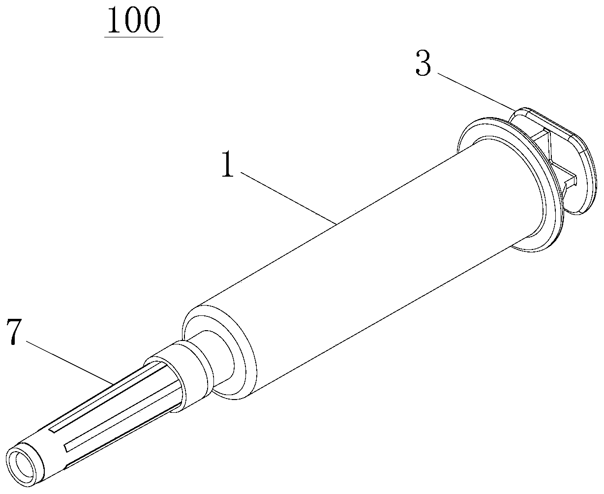
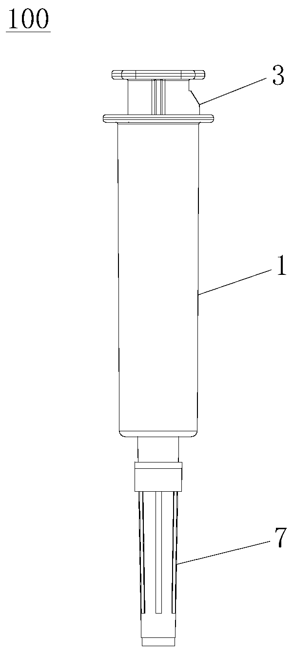
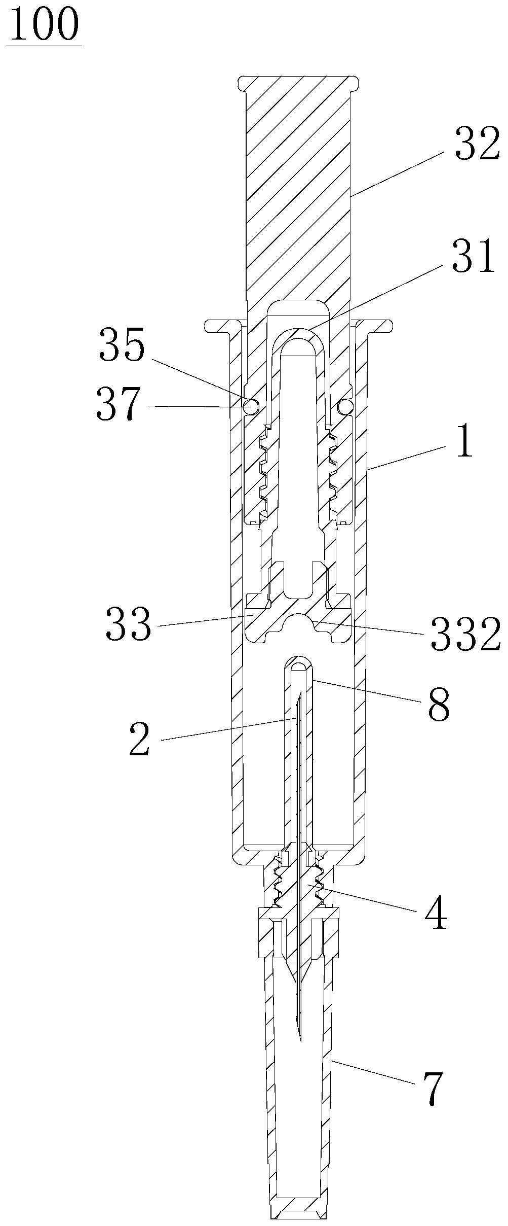
[0062] like Figure 1 to Figure 16 As shown, the exemplary embodiment of the present invention provides an aqueous humor collection device 100 , and the aqueous humor collection device 100 includes an outer cylinder 1 , a puncture needle 2 and a liquid collection tube assembly 3 . The outer cylinder body 1 is provided with a puncture needle installation end and a liquid collection tube installation end located at both axial ends. The puncture needle 2 is fixedly installed on the installation end of the puncture needle and is provi...


PUM


Abstract

The invention discloses an aqueous humor collection device. The aqueous humor collection device comprises an outer cylinder, a puncture needle and a liquid collecting pipe assembly, wherein the outer cylinder is provided with a puncture needle mounting end and a liquid collecting pipe mounting end; the puncture needle is inserted in the puncture needle mounting end and comprises a puncture needle outer end and a puncture needle inner end; the liquid collecting pipe assembly is pluggably and movably inserted in an outer cylinder cavity and comprises a liquid collecting pipe and a pipe stopper; a ventilation structure is formed between the liquid collecting pipe assembly and the inner peripheral wall of the outer cylinder, and can be communicated with a cylinder cavity area, between the puncture needle inner end and the pipe stopper, of the outer cylinder cavity, and the aqueous humor collection device also comprises a limiting buffer structure used for limiting radial displacement of the liquid collecting pipe assembly and used for forming contact damping between the liquid collecting pipe assembly and the inner peripheral wall of the outer cylinder. The aqueous humor collection device can control the drainage speed of aqueous humor during puncture, avoid the contamination of the aqueous humor after collection is completed and the waste caused by transfer of the aqueous humor, and can ensure the insertion and pulling stability of the liquid collecting pipe assembly, thereby being conductive to improving the safety, reliability and detection accuracy.

Description

technical field [0001] The invention relates to the technical field of medical appliances, in particular to an aqueous humor collection device. Background technique [0002] Anterior chamber puncture is a medical technique that pierces the cornea of ​​the eyeball with instruments to allow aqueous humor to flow out. It has important application value in clinical research in ophthalmology. Drain the room. [0003] For now, there is no unified special equipment and consumables for the implementation of anterior chamber puncture. In actual clinical work, 1ml syringe needles are often used as anterior chamber puncture needles. However, in the process of puncturing with the 1ml syringe needle, it is difficult to control the drainage speed of aqueous humor. When the liquid is drained too fast, it will cause a rapid drop in intraocular pressure, and even cause other complications in severe cases. In addition, since the aqueous humor in the syringe cavity needs to be further transf...

Claims


Application Information

Patent Timeline
Patent Type & Authority Patents(China)
IPC IPC(8): A61F9/007
CPCA61F9/00736A61F9/00781
Inventor 赵潺
Owner BEIJING SIGHTNOVO MEDICAL TECH CO LTD
Learn More