Wood board fixed-length cutting device

A cutting device and fixed-length technology, applied in feeding devices, clamping devices, sawing components, etc., can solve the problems of low efficiency of manual feeding and inability to achieve continuous fixed-length cutting, and achieve good continuous processing performance and cutting efficiency. High and stable effect

Inactive Publication Date: 2019-09-17
李锋
View PDF11 Cites 27 Cited by
  • Summary
  • Abstract
  • Description
  • Claims
  • Application Information

AI Technical Summary

Problems solved by technology

But when existing plank cutting machine is in use, basically all is to draw a cutting line on the plank, then manually feeds, and makes the cutting sheet of cutting machine cut it; Low, unable to achieve continuous cut-to-length

Method used


Image

  • Wood board fixed-length cutting device
  • Wood board fixed-length cutting device
  • Wood board fixed-length cutting device

Examples


specific Embodiment approach 1

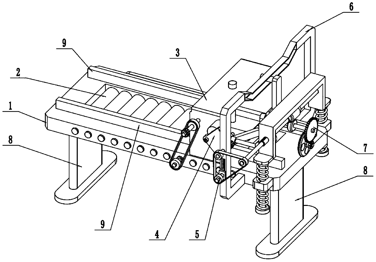
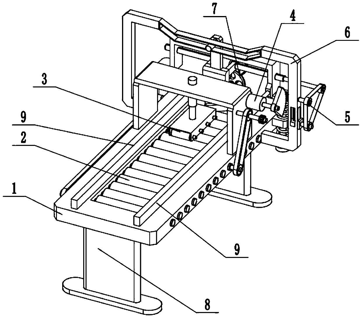
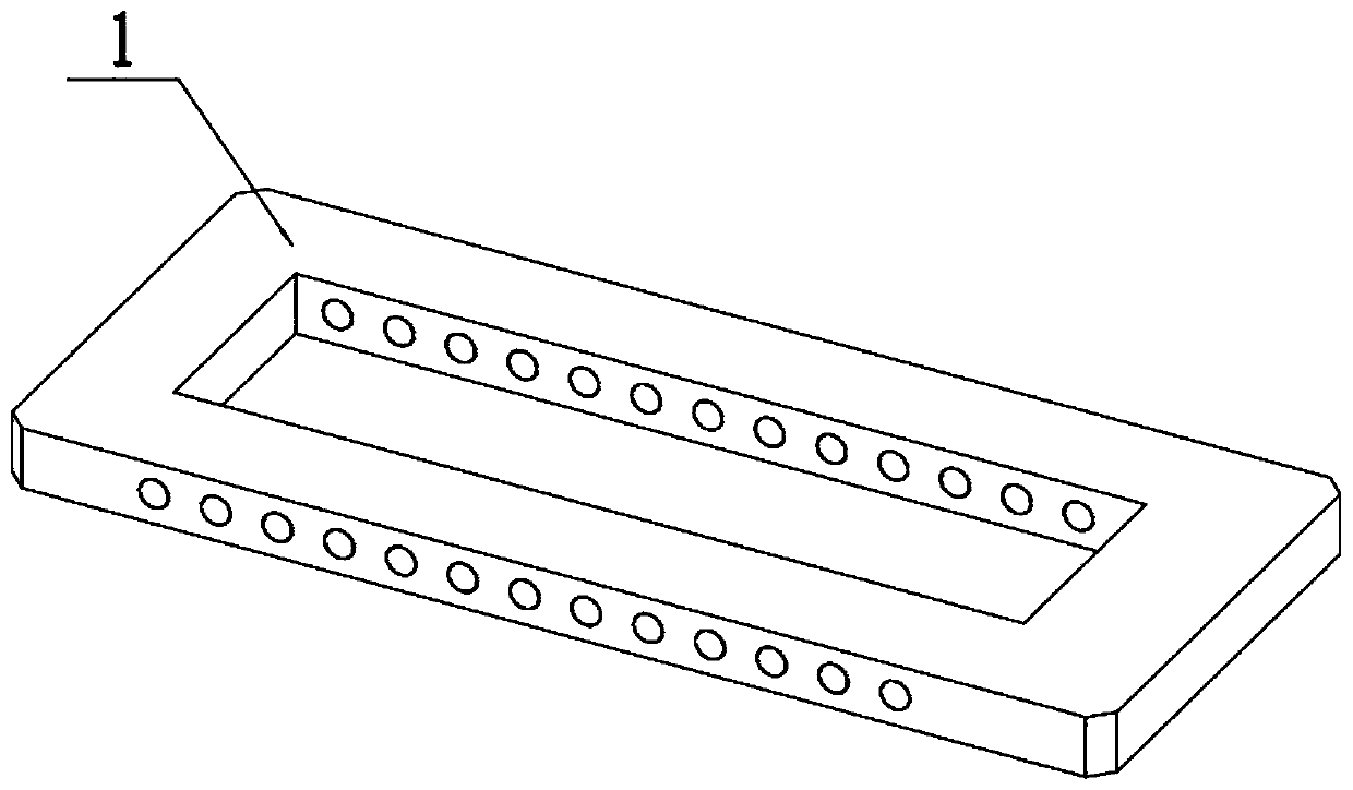
[0032] Such as Figure 1-12As shown, a wood board fixed-length cutting device includes a frame 1, a board conveying roller group 2, a pressure roller 3, a driving mechanism 4, a tension linkage wheel 5, a guide frame 6, a cutting mechanism 7, legs 8 and side Baffle plate 9, a support leg 8 is respectively fixed at the front and rear ends of the bottom surface of the frame 1; a side baffle plate 9 is respectively fixed at the left and right ends of the top surface of the frame 1; In the installation groove on the top surface of the frame 1, the plate conveying roller group 2 is located between two side baffles 9; 3; the drive mechanism 4 is connected to the side end of the pinch roller 3; the drive mechanism 4 is connected to the plate conveying roller set 2 and the tension linkage wheel 5; the tension linkage wheel 5 is connected to the guide frame 6; the guide frame 6 is installed on the front end of the frame 1; the tension linkage wheel 5 is connected to the cutting mechan...

specific Embodiment approach 2

[0034] Such as Figure 1-12 As shown, the pressure roller 3 includes a gantry 301, an electric push rod 302, a pressure roller body 303, a pressure roller shaft 304 and a pressure roller seat 305; the gantry 301 is fixed on the front end of the top surface of the frame 1 The upper and lower ends of the electric push rod 302 are fixedly connected with the gantry 301 and the pressure roller seat 305 respectively; the pressure roller body 303 is provided with a plurality of pressure roller bodies 303 arranged side by side through a plurality of pressure roller shafts 304 Rotation fits in the lower end of pressure roller seat 305. When the pressure roller 3 is working, it can control the downward movement distance of the pressure roller body 303, the pressure roller shaft 304 and the pressure roller seat 305 through the electric push rod 302 according to the thickness of the wood board, and then press the pressure roller body 303 on the wood board The upper end of the board is cl...

specific Embodiment approach 3

[0036] Such as Figure 1-12 As shown, the plate conveying roller set 2 includes a conveying roller 201, a roller shaft 202, a synchronous pulley 203, a first wheel shaft 204, a first sprocket 205, a second sprocket 206, a second wheel shaft 207 and a first gear 208 The roller shafts 202 are provided with a plurality of them, and the plurality of roller shafts 202 are rotated side by side and fitted on the frame 1 from front to back; a conveying roller 201 is respectively fixed on the plurality of roller shafts 202, and a plurality of conveying rollers 201 are all located on the machine frame In the installation groove on the top surface of frame 1; the left ends of multiple roller shafts 202 are respectively fixed with a synchronous pulley 203, and the synchronous belt pulleys 203 are connected by a synchronous toothed belt transmission; the right end of a roller shaft 202 is fixedly connected The first axle 204 is fixedly connected to the first sprocket 205 on the first axle ...


PUM


Abstract

The invention relates to the field of wood processing, in particular to a wood board fixed-length cutting device. The wood board fixed-length cutting device comprises a rack, a board conveying roller assembly, a pressure roller, a driving mechanism, a tensioning linkage wheel, a guide frame, a cutting mechanism, supporting legs and side baffles; the supporting legs are fixed at the front end and the rear end of the bottom face of the rack separately; the side baffles are fixed at the left end and the right end of the top face of the rack separately; the board conveying roller assembly is connected in an installation groove in the top face of the rack; the board conveying roller assembly is located between the two side baffles; the pressure roller is arranged at the front end of the top face of the rack; and the board conveying roller assembly is connected to the side end of the pressure roller. According to the wood board fixed-length cutting device, continuous fixed-length cutting is carried out on a wood board by adopting an automatic feeding and fixed length cutting mode, the cutting efficiency is high, and the labor force is low.

Description

technical field [0001] The invention relates to the field of wood processing, in particular to a wood board fixed-length cutting device. Background technique [0002] Wood processing, using wood as raw material, is processed by mechanical or chemical methods, and its products still maintain the basic characteristics of wood. Wood boards are wood boards made of complete wood. [0003] When the wood board is actually used, it needs to be cut to make the wood board into a usable specification. The wood board cutting machine is a tool commonly used when cutting the wood board. Specifications. However, when the existing wood cutting machines are in use, they basically draw a cutting line on the plank, and then manually feed the material so that the cutting blades of the cutting machine can cut it; Low, unable to achieve continuous cut-to-length. Contents of the invention [0004] The purpose of the present invention is to provide a wood board fixed-length cutting device, whi...

Claims


Application Information

Patent Timeline
Patent Type & Authority Applications(China)
IPC IPC(8): B27B5/06B27B5/29B27B31/00B27B29/02
CPCB27B5/06B27B5/29B27B29/02B27B31/003
Inventor 李锋
Owner 李锋
Why Eureka
Try Eureka