
Motion guide device of injection molding motor template and injection molding machine

A guide device and template technology, applied in the field of injection molding equipment, can solve the problems of deterioration of accuracy, occupation of space in injection molding workshop, poor processing accuracy, etc., and achieve the effect of improving lateral guiding accuracy, improving forward guiding accuracy, and cost-effectiveness of large land use.

Pending Publication Date: 2019-09-17
LIUZHOU KAIYU PLASTIC INJECTION MACHINERY CO LTD
View PDF2 Cites 1 Cited by
  • Summary
  • Abstract
  • Description
  • Claims
  • Application Information

AI Technical Summary

Problems solved by technology

This structure has the following problems: (1) Since the pull rod is the core part that generates the clamping force, its material and manufacturing costs are very expensive. The guiding method disclosed in this invention makes the length of the two pull rods longer and the cost is very high; ( 2) The extension of the tie rod leads to the lengthening of the machine base, which increases the material and manufacturing costs; (3) This method increases the length of the injection molding machine and takes up more space in the injection molding workshop
This structure has the following problems: (1) the adjustment between the lateral sliding foot and the lateral guide rail can only be adjusted by increasing or decreasing the adjustment pad, which makes the adjustment range of the lateral sliding foot smaller; (2) The sliding foot plate is located on the inner side of the moving template, making adjustment difficult and not conducive to quick adjustment; (3) The structure of the side guide rail is not mentioned in the guide structure, and whether the structure of the side guide rail can guarantee the overall guidance is not considered. Performance and manufacturing cost issues
This method has the following disadvantages: (1) Along the length direction of the tie rod, four guide rails need to be arranged on the frame, that is, two forward slide rails and two lateral slide rails. It is necessary to ensure high shape and position tolerance with the lateral slideway, so the processing of this structure needs to be processed in the CNC machining center, the processing cost is very high, and the efficiency is low; (2) The base of the injection molding machine is generally a welded structure , there will be a very large deformation after welding. Even after aging or stress relief treatment, there will be deformation problems in subsequent use, which makes it more difficult to ensure the shape and position tolerances of the forward and lateral slideways, resulting in guiding accuracy. deterioration
[0008] 4. Linear rolling guide rail guidance, the guide structure is limited by the low quality of domestic steel materials, poor aging treatment effect, poor processing accuracy and high cost of high-load line rails. In fact, it is difficult to achieve the ideal guiding effect

Method used


Image

  • Motion guide device of injection molding motor template and injection molding machine
  • Motion guide device of injection molding motor template and injection molding machine
  • Motion guide device of injection molding motor template and injection molding machine

Examples


Embodiment Construction

[0044] Below, the present invention will be further described in conjunction with the accompanying drawings and specific implementation methods. It should be noted that, under the premise of not conflicting, the various embodiments described below or the technical features can be combined arbitrarily to form new embodiments. .

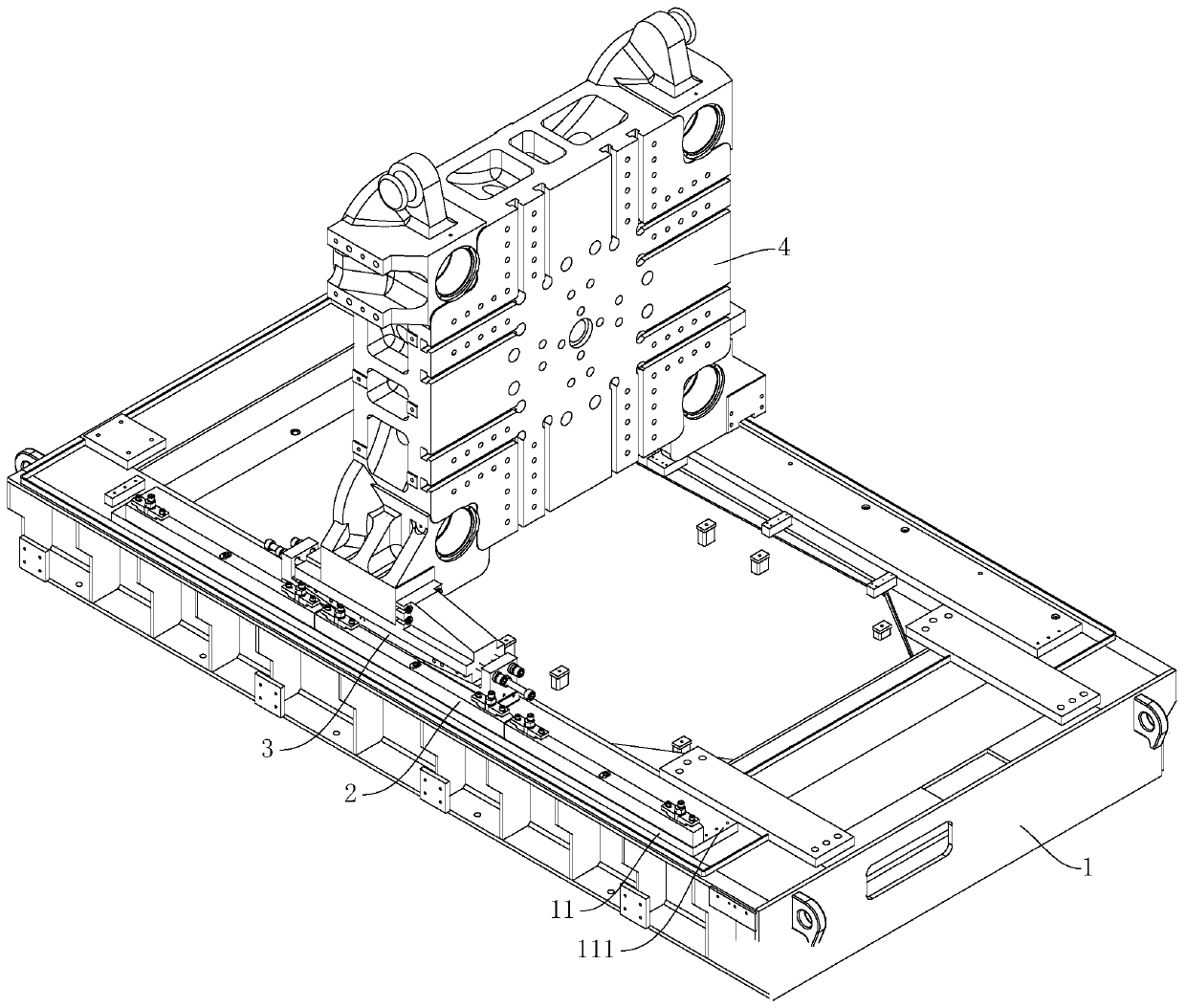
[0045] see figure 1 , shows a motion guide device for injection molding motorized templates in a preferred embodiment of the present invention, including a frame 1, a lateral guide assembly 2 and two sets of support assemblies 3, wherein the top surface of the frame 1 is provided with two The slideways 111 are parallel to each other, and the two slideways 111 are respectively arranged on both sides of the top surface of the frame 1, and the two sides of the top surface of the frame 1 are provided with at least two groups along the length direction of the slideways 111. The lateral guide assemblies 2 arranged in sequence, the support assemblies 3 are u...


PUM


Abstract

The invention discloses a motion guide device of an injection molding motor template and an injection molding machine. The motion guide device comprises a rack and a lateral guide assemblies, a slideway is arranged on the top surface of the rack, the slideway is used for being in sliding fit with the movable template, at least two groups of lateral guide assemblies are arranged on the two sides of the rack, the side guide assemblies comprise first guide plates, eccentric pins and first fastening screws, the inner side surface of the first guide plates are used for being in sliding fit with the outer side surface of the movable templates, the two ends of the first guide plates are respectively provided with first guide grooves, the eccentric pins comprise first connecting columns and second connecting columns which are connected in sequence, the central axis of the second connecting columns are offset with the central axis of the first connecting columns, the outer diameter of the second connecting columns are smaller than the outer diameter of the first connecting columns, so that parting surfaces are formed between the first connecting columns and the second connecting columns, the eccentric pins penetrate through the first guide grooves and are inserted into the rack, the first fastening screws are used for connecting the eccentric pins, the first guide plates and the rack together. According to the motion guide device, the guide precision is more easily ensured.

Description

technical field [0001] The invention relates to the technical field of injection molding equipment, in particular to a motion guide device and an injection molding machine for an injection molding motorized template. Background technique [0002] At present, most of the clamping devices used in injection molding equipment and die-casting molding equipment adopt a two-platen clamping structure (referred to as a two-platen machine). The two-plate injection molding machine generally includes a movable template, a fixed template, a mold-moving cylinder fixed on the fixed template, a tie rod connected between the movable template and the fixed template and for the movable template to move on it, a clamping cylinder and a brake mechanism, etc. , the action process of a typical two-platen injection molding machine is as follows: the moving platen is driven by the mold-moving cylinder fixed to the fixed platen to move quickly until the mold is closed. The cylinder pulls the tie rod...

Claims


Application Information

Patent Timeline
Patent Type & Authority Applications(China)
IPC IPC(8): B29C45/26
CPCB29C45/2606
Inventor 徐峻丁建华谢汝彬莫品荣甘志猛
Owner LIUZHOU KAIYU PLASTIC INJECTION MACHINERY CO LTD
Learn More