
Top water adding humidifier

A humidifier and water tank technology, used in air humidification systems, heating methods, lighting and heating equipment, etc., can solve the problems of insignificant increase in fog output and low fog output, achieve large fog output, and increase convection opportunities. , The effect of the overall structure is simple

Pending Publication Date: 2019-09-17
BEAR ELECTRICAL APPLIANCE CO LTD
View PDF1 Cites 2 Cited by
  • Summary
  • Abstract
  • Description
  • Claims
  • Application Information

AI Technical Summary

Problems solved by technology

[0002] In order to meet the user's requirements for mist output, existing humidifiers often use energy-gathering devices or energy-gathering rings in the humidifier to gather the vibration energy of the atomizing sheet to enhance the atomization capacity, but the actual increase in mist output is not It is not obvious, but there is still the defect of low mist output. This is because: when the water level in the water tank of the humidifier is high, the space above the water level in the atomization chamber is small, which limits the airflow and mist discharged from the air outlet of the air duct. The water mist in the atomization chamber produces sufficient convection, so that the water mist cannot be brought out in time and the mist output is low; when the water level in the water tank of the humidifier is low, although the space above the water level in the atomization chamber becomes larger, due to The water mist is concentrated on the water surface of the atomization chamber, and the distance between a large amount of water mist and the air outlet of the air duct is relatively long. The position of the water surface of the atomization chamber also restricts the sufficient convection between the airflow discharged from the air outlet of the air duct and the water mist on the water surface of the atomization chamber, resulting in a low mist output

Method used


Image

  • Top water adding humidifier
  • Top water adding humidifier
  • Top water adding humidifier

Examples


Embodiment Construction

[0021] In order to further explain the technical means and functions adopted by this application to achieve the predetermined purpose, the specific implementation, structure, features and functions according to this application will be described in detail below in conjunction with the drawings and preferred embodiments. In the following description, different "one embodiment" or "embodiment" do not necessarily refer to the same embodiment. Furthermore, the particular features, structures, or characteristics of one or more embodiments may be combined in any suitable manner.

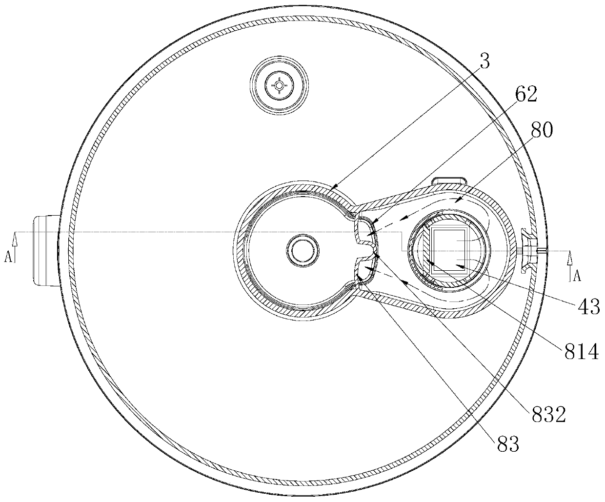
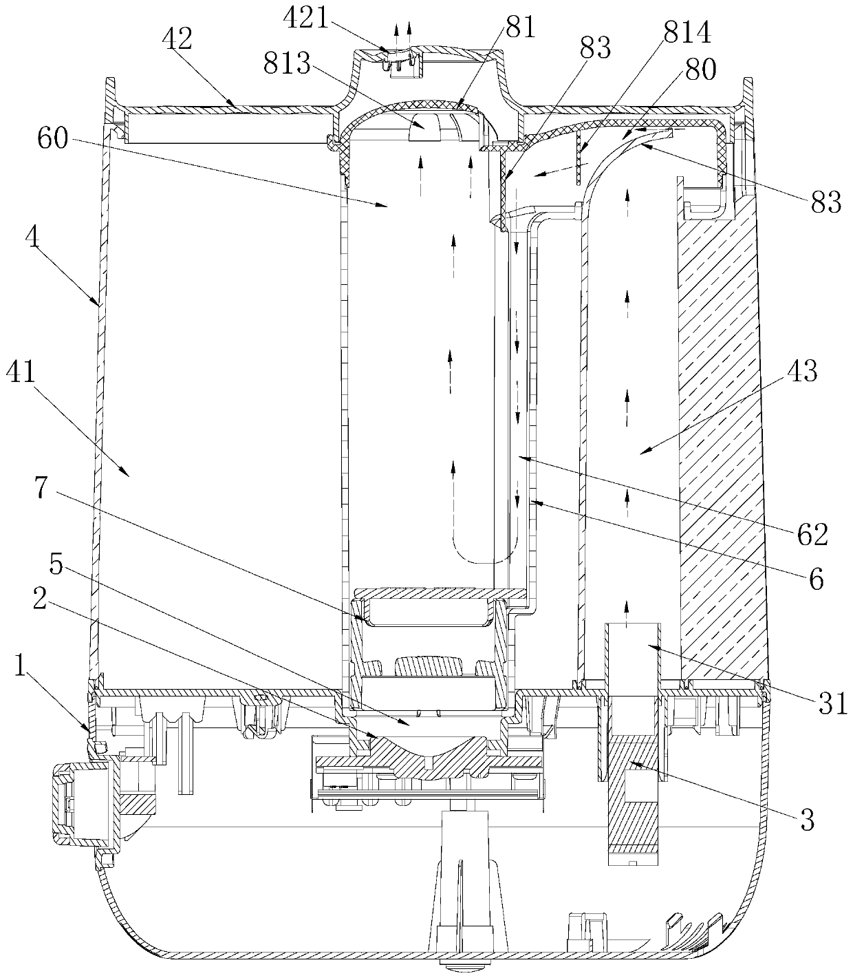
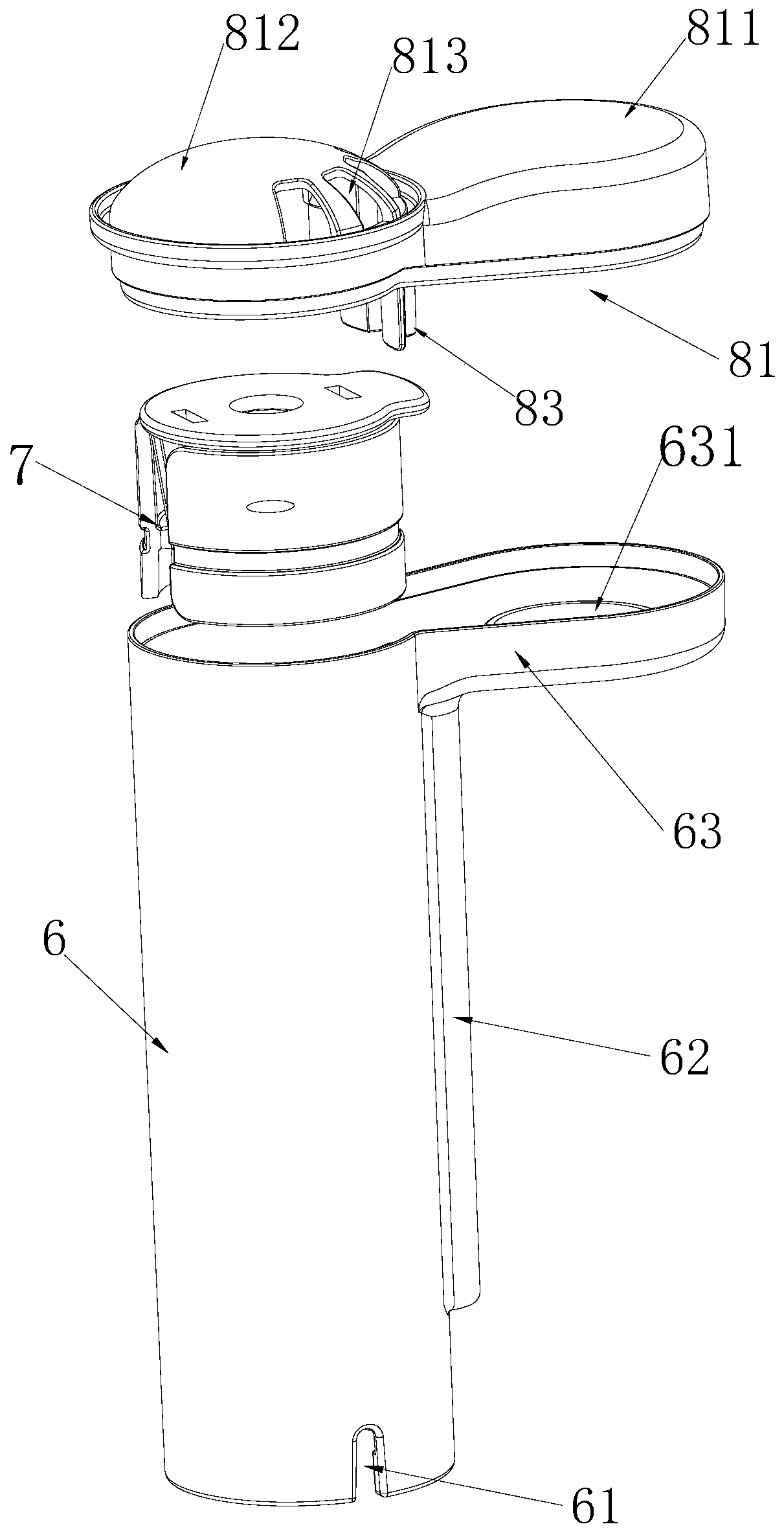
[0022] combine Figure 1-Figure 4 As shown, the present invention discloses an upper water humidifier comprising: base 1; 42, the water tank cover 42 is provided with a mist outlet 421; the atomization chamber 5 communicated with the water storage chamber 41, and the bottom of the atomization chamber 5 is provided with a mist for vibrating water into water mist The carburetor 2; the air duct 43 located o...


PUM


Abstract

The invention discloses a top water adding humidifier. The top water adding humidifier comprises a base, a water tank arranged on the base and internally provided with a water storage chamber, an atomization chamber communicating with the water storage chamber, an air passage arranged on one side of the water storage chamber, a wind guide cover, a wind guide passage and a flow guide plate; the bottom portion of the atomization chamber is provided with an atomizer; a fan is arranged at the bottom of the air passage, and an air outlet is formed in the upper tail end of the air passage; and the wind guide cover is buckled to the air passage and the atomization chamber, one end of the flow guide plate is arranged on the top wall of the wind guide cover, the other end of the flow guide plate extends downwards into the atomization chamber, the wind guide passage communicates with the air outlet and the upper tail end of the atomization chamber, airflow discharged from the fan is guided to the flow guide plate through the wind guide passage, and the flow guide plate guides the airflow to the lower tail end of the atomization chamber. The top water adding humidifier is simple in overall structure and stable and reliable in work, and the large fog amount can be maintained regardless of the water level in the water tank.

Description

technical field [0001] The invention relates to household appliances, in particular to an upper water humidifier. Background technique [0002] In order to meet the user's requirements for mist output, existing humidifiers often use energy-gathering devices or energy-gathering rings in the humidifier to gather the vibration energy of the atomizing sheet to enhance the atomization capacity, but the actual increase in mist output is not It is not obvious, but there is still the defect of low mist output. This is because: when the water level in the water tank of the humidifier is high, the space above the water level in the atomization chamber is small, which limits the airflow and mist discharged from the air outlet of the air duct. The water mist in the atomization chamber produces sufficient convection, so that the water mist cannot be brought out in time and the mist output is low; when the water level in the water tank of the humidifier is low, although the space above th...

Claims


Application Information

Patent Timeline
Patent Type & Authority Applications(China)
IPC IPC(8): F24F6/12F24F13/08
CPCF24F6/12F24F13/08
Inventor 李一峰黎鉴池梁海权
Owner BEAR ELECTRICAL APPLIANCE CO LTD
Learn More