
High-stability adjustable spiral planer

A high-stability planer technology, applied in the direction of processing machines for manufacturing flat surfaces, wood processing appliances, workpiece feeding devices, etc., can solve the problems of cumbersome installation, redundant center of gravity of the transmission mechanism, increased maintenance costs, etc., and achieve adjustment Precise and stable, convenient and stable adjustment, and the effect of improving processing quality

Inactive Publication Date: 2019-09-20
青岛魏氏精工机械有限公司
View PDF0 Cites 0 Cited by
  • Summary
  • Abstract
  • Description
  • Claims
  • Application Information

AI Technical Summary

Problems solved by technology

However, in actual use, it is found that the same screw planer cannot achieve high stability and adaptability to processing wood of different widths; There are no restrictions on the horizontal left and right directions on the conveyor belt. During the planing process, the wood is easily shifted in the direction of transportation due to external uncontrollable factors such as density and thickness, so there is no guarantee Wood has been kept in a stable state during processing, which will affect the quality stability and precision requirements during wood processing
In addition, the lift-type planing parts need a matching lifting mechanism, resulting in redundant transmission mechanisms and a high center of gravity of the equipment, which is inconvenient to maintain and use; finally, the blade-type cutter shafts in the prior art often use closed holes Fixing the blade with screws is not only cumbersome to install, but also due to the uneven rigidity of the blade during the cutting process, individual blades are prone to damage, affecting product quality and increasing maintenance costs

Method used


Image

  • High-stability adjustable spiral planer
  • High-stability adjustable spiral planer

Examples


Embodiment Construction

[0020] The specific implementation manners of the present invention will be further described in detail below in conjunction with the accompanying drawings and embodiments. The following examples are used to illustrate the present invention, but are not intended to limit the scope of the present invention.

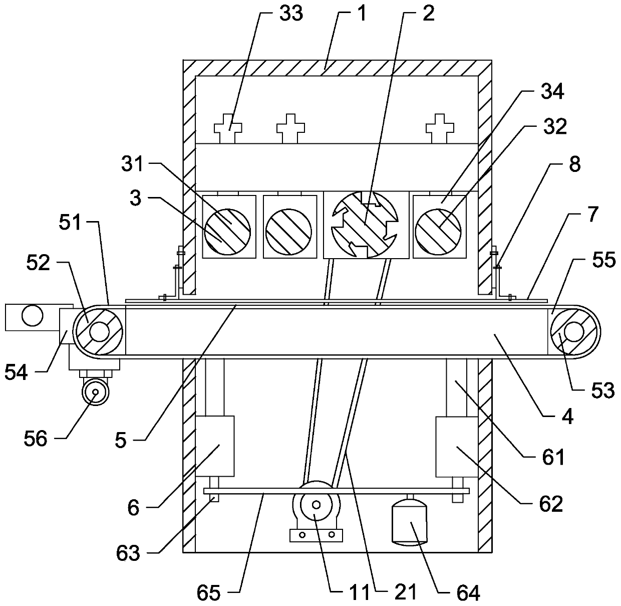
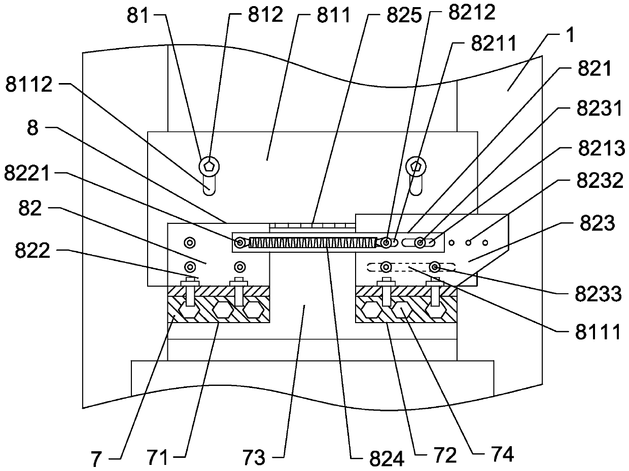
[0021] Such as figure 1 and figure 2 As shown, a high-stability adjustable spiral planer includes a planer body 1, a planer module and a feeding module. The feeding channel, the planing module includes a planing spindle 2 and the pressure roller 3; the feeding module includes a worktable 4, a conveying mechanism 5 and a lifting mechanism 6, and the working table 4 can be lifted and installed on the planer through the lifting mechanism 6 On the feeding channel of the body 1 , the conveying mechanism 5 includes a conveyor belt 51 and a power source, and the conveyor belt 51 passes through the feeding channel and is installed on the workbench 4 . The wood enters the feedi...


PUM


Abstract

The invention provides a high-stability adjustable spiral planer. The high-stability adjustable spiral planer comprises a planer body, a planing module and a feeding module, wherein the planing module comprises a planing main shaft and a pressing roller; a feeding module comprises a workbench, a conveying mechanism, a lifting mechanism and an adjusting mechanism; the conveying mechanism comprises a conveying belt and a power source; the adjusting mechanism comprises positioning plates and adjusting assemblies; the adjusting assemblies are symmetrically arranged at a position, above the conveying belt at two ends of a feeding channel, on the outer wall of the planer body; the positioning plates are arranged in parallel with the conveying belt at an up-down interval; the positioning plates comprise a fixed plate and an adjusting plate which are horizontally spaced; a feeding positioning channel is formed between the fixed plate and the adjusting plate; and the adjusting assemblies comprises a vertical adjusting assembly and a horizontal adjusting assembly. The high-stability adjustable spiral planer is capable of conveying wood with different thicknesses and widths, higher in adaptability and application rate, higher and more stable in working efficiency and more compact in structure.

Description

technical field [0001] The invention belongs to the technical field of wood processing equipment, in particular to a high-stability adjustable spiral planer. Background technique [0002] Spiral planer is a kind of equipment for surface processing of wood. It can plan the surface of wood to remove uneven protrusions, shallow pits, oxide layers and shallow marks on the wood surface. Flat and has a wide range of applications in various industries. The spiral planer in the prior art is usually composed of a lifting planing part and a fixed feeding part. The feeding part is changed from a traditional unstable feeding roller to a conveyor belt. The conveyor belt provides support for the wood during transportation, which can ensure The medium speed is stable and the load is uniform, which can effectively realize the transportation function in the wood processing process. However, in actual use, it is found that the same screw planer cannot achieve high stability and adaptability...

Claims


Application Information

Patent Timeline
Patent Type & Authority Applications(China)
IPC IPC(8): B27C1/00B27C1/12B27C1/14
CPCB27C1/00B27C1/12B27C1/14
Inventor 魏朋
Owner 青岛魏氏精工机械有限公司
Learn More