A non-burning brick-making equipment for making construction waste into bricks

A construction waste and equipment technology, applied in the field of non-fired brick making equipment, can solve the problems of difficult to control the amount of materials and large deviation of brick density, so as to reduce the trouble of manual cleaning, the quality of finished bricks is good, and the production efficiency of equipment is high Effect

Active Publication Date: 2021-06-18
杭州钱江新城市政园林建设有限公司 +1
View PDF0 Cites 1 Cited by
  • Summary
  • Abstract
  • Description
  • Claims
  • Application Information

AI Technical Summary

Problems solved by technology

Moreover, the existing brick-making method is a horizontal mold channel and a horizontal extrusion molding method. It is also difficult to control the amount of materials, and the density of the bricks produced has a large deviation.

Method used


Image

  • A non-burning brick-making equipment for making construction waste into bricks
  • A non-burning brick-making equipment for making construction waste into bricks

Examples


Embodiment 1

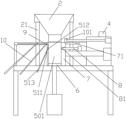
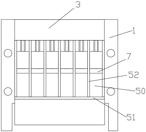
[0033] A non-fired brick-making equipment for making construction waste into bricks, including a machine 1, a silo 2, a cabinet 3 and a control device 4, and the machine is provided with one or more upper and lower sides and one end open The semi-frame-shaped mold cavity road 50, the mold cavity road includes a road end plate 51 and a road wall plate 52, the bottom of the mold cavity road is provided with a bottom pressure plate 6 that can be raised and lowered along the mold cavity road, opposite to the road end plate A movable side pressure plate 7 is inserted into the open end of the open end, and the bottom pressure plate, the side pressure plate and the mold cavity channel cooperate to form a mold cavity 501. On the mold cavity, a through hole is opened on the side pressure plate, and a resisting plate 8 that can extend into the mold cavity is arranged in the through hole.

[0034] Corresponding to the height of the abutment plate, there is a alignment hole 511 on the end...

Embodiment 2

[0038] The difference from the above embodiment is that the outer side of the channel end plate is provided with a sloping material guide plate 513 corresponding to the lower edge of the alignment hole, and a material collecting structure is arranged below the sloping material guide plate at the bottom of the machine table. The collecting structure can be a structure such as a material box or a material conveyor belt.

[0039]The feed bin is set up and down above the machine platform through a lifting mechanism, and the feed bin is set on the machine table through lifting feet 21, and the lifting feet are connected with telescopic cylinders. The lifting equipment of the material bin is convenient for the observation, operation or maintenance of the mold cavity, and at the same time, the bricks can be taken out from the top of the mold cavity. The top of the cavity is removed.

Embodiment 3

[0041] The difference from the above-mentioned embodiment is that a height limit alarm device 9 for controlling the automatic feeding amount of the feeding bin is provided in the area of ​​the cavity channel higher than the abutment plate. When the amount of material is greater than the amount of bricks, it can be controlled by the height limit alarm device, which can be an infrared induction device or a touch switch. Once it reaches this position, it will send a signal to the control device. The silo stops feeding.


PUM


Abstract

The invention belongs to the field of brick making, and in particular relates to a burn-free brick making equipment for making construction waste into bricks. Including machine table, silo, cabinet and control device, the machine table is equipped with one or more semi-frame-shaped mold cavity channels with upper and lower sides and one end open. The cavity channel includes channel end plates and channel wall plates, and the bottom of the cavity channel There is a bottom pressing plate that can be raised and lowered along the mold cavity road, and a movable side pressing plate is inserted into the open end opposite to the end plate of the road. The opening, at least the feeding opening, is liftable against the mold cavity, and a through hole is opened on the side pressing plate, and a supporting plate that can extend into the mold cavity is provided in the through hole. This application has completely changed the traditional way of making bricks from construction waste. The vertical top is sealed with a top plate, and the bottom bottom plate pushes materials to make bricks, and the discharge port of the silo can not only reach the mold cavity. The frame of the present application is neat and tidy, and the material loss is less, and a small amount of surplus material pushed out by the abutting plate also leaks through the through hole for centralized recovery.

Description

technical field [0001] The invention belongs to the field of brick making, and in particular relates to a burn-free brick making equipment for making construction waste into bricks. Background technique [0002] In the process of building construction and demolition, a large amount of construction waste will be produced, which contains recyclable metal materials, and more of them are slag and gravel. In the past, slag and gravel were treated by landfill. In order to avoid waste and realize Resources are used for recycling. At present, these slag and gravel are crushed by crushing equipment, and then other materials of a certain formula are added to the crushed material, and then fired without firing. The existing brick making machine is prone to material overflow during the process of filling or extruding materials in the mold cavity, so that the whole brick making machine is surrounded by materials. First, it produces waste, second, it is inconvenient to clean, and third, i...

Claims


Application Information

Patent Timeline
Patent Type & Authority Patents(China)
IPC IPC(8): B28B3/06B28B13/02
CPCB28B3/06B28B13/0215
Inventor 陈鑫周良燕王激扬金斌斌曾强
Owner 杭州钱江新城市政园林建设有限公司
Why Eureka
Try Eureka