Control cabinet testing platform encoder single-phase single counting model

A test platform and encoder technology, applied in the field of elevators, can solve problems such as troublesome movement and handling of encoders and control cabinets, unstable operation of encoders, damage to electrical appliances such as encoders, etc., so as to avoid the appearance of cross-inductance and facilitate stable work , observe the intuitive effect

Inactive Publication Date: 2019-09-20
JIANGSU MARITIME INST +1
View PDF0 Cites 0 Cited by
  • Summary
  • Abstract
  • Description
  • Claims
  • Application Information

AI Technical Summary

Problems solved by technology

[0002] With the continuous improvement of modern people's material living standards, the scope of use of elevators is also expanding. The elevator control cabinet plays a decisive role in the normal operation of the elevator. Therefore, the control cabinet and its internal encoders, controllers, counters and other components The normal operation of the elevator has brought guarantees to the operation of the elevator. The use of the encoder is mainly to compile and convert the signal or data into a signal form that can be used for communication, transmission, and storage. It is usually connected to the traction motor in a rotating manner. Connection, when the traditional encoder is running, a large amount of heat energy will be generated when the electrical appliances inside the control cabinet are running, and this heat cannot be eliminated, resulting in damage to the encoder and other electrical appliances inside the control cabinet due to excessive heat. Due to the high frequency of elevator up and down, the traditional encoder control cabinet lacks decompression and buffer components, resulting in extremely unstable operation of the control cabinet and the internal encoder, which is easy to cause damage to electrical appliances, etc. The lack of moving components makes the encoder And the control cabinet becomes very troublesome in the process of moving and handling before and after use

Method used


Image

  • Control cabinet testing platform encoder single-phase single counting model
  • Control cabinet testing platform encoder single-phase single counting model
  • Control cabinet testing platform encoder single-phase single counting model

Examples


Embodiment Construction

[0022] The specific embodiments of the present invention will be described below with reference to the accompanying drawings.

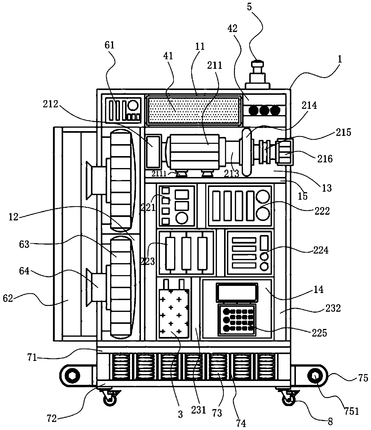
[0023] like figure 1 As shown, the present invention provides a single-phase single-counting model of a control cabinet test platform encoder, including a box body 1, a control unit, a backup power supply 3, a display unit, an alarm buzzer 5, a temperature control unit, a buffer unit and four Move wheel 8.

[0024] The box body 1 is hollow, and the interior is divided into a first installation area 11 , a second installation area 12 , a third installation area 13 and a fourth installation area 14 . The first installation area 11 is located at the top of the box 1, the second installation area 12 is located on the side below the first installation area 11, and the third installation area 13 and the fourth installation area 14 are located in the first installation area from top to bottom. The other side below zone 11.

[0025] The control unit includ...


PUM


Abstract

The invention discloses a control cabinet testing platform encoder single-phase single counting model. The control cabinet testing platform encoder single-phase single counting model comprises a box body, a control unit, a standby power supply, a display unit, an alarm buzzer, a buffer unit and multiple moving wheels; the control unit comprises a traction motor, a high-speed counter, a turbine speed reducer, a traction inertia rope wheel, a coupling, a rotary encoder, a frequency converter, an alternating-current contactor, an electric leakage releaser, an inverter and a controller; the display unit comprises a RGB information display screen arranged in a first mounting area and connected with the controller for displaying an operating state of the model; the alarm buzzer is fixedly mounted at the outer top of the box body, and is connected with a controller; the controller drives the alarm buzzer to give an alarm; the buffer unit is positioned under the box body; and the multiple moving wheels are arranged at the bottom of a lower buffer plate. The control cabinet testing platform encoder single-phase single counting model has the advantages of reasonable structure, quick heat dissipation, stable operation and direct observation.

Description

technical field [0001] The invention belongs to the field of elevators, and relates to an elevator control cabinet test platform technology, in particular to a control cabinet test platform encoder single-phase single-count model. Background technique [0002] With the continuous improvement of modern people's material living standards, the scope of use of elevators has also continued to expand. The elevator control cabinet plays a decisive role in the normal operation of the elevator. Therefore, the control cabinet and its internal components such as encoders, controllers, counters and other components play a decisive role. The normal operation of the elevator guarantees the operation of the elevator. The use of the encoder is mainly by programming and converting the signal or data into a signal form that can be used for communication, transmission and storage. It is usually connected to the traction motor in a rotating way. When the traditional encoder is running, a large ...

Claims


Application Information

Patent Timeline
Patent Type & Authority Applications(China)
IPC IPC(8): B66B1/06B66B1/34B66B5/00B66B7/08B66B11/04F16F15/04H05K7/20
CPCB66B1/06B66B1/3423B66B5/0031B66B7/08B66B11/043F16F15/04H05K7/20145H05K7/20172H05K7/20209Y02B50/00
Inventor 王景良季明丽夏慧
Owner JIANGSU MARITIME INST
Why Eureka
Try Eureka