
A barrier-free cleaning device for abandoned piles

A cleaning device and barrier-free technology, applied in sheet pile wall, construction, infrastructure engineering and other directions, can solve the problems of increasing the load of lifting equipment, increasing the labor intensity of workers, blocking the tunneling of shield machines, and reducing the lifting weight. , The effect of improving lifting efficiency and reducing labor intensity

Active Publication Date: 2020-06-23
甘肃九州岩土工程有限公司
View PDF9 Cites 1 Cited by
  • Summary
  • Abstract
  • Description
  • Claims
  • Application Information

AI Technical Summary

Problems solved by technology

[0003] However, the tunnel excavation route often encounters old foundation piles that existed in previous foundation projects, which hinders the excavation of the shield machine. Therefore, it is necessary to remove the waste piles of the construction
At present, there are many methods of pulling out waste foundation piles, and because the waste foundation piles are in the soil layer for a long time, the adsorption and bonding force between the foundation piles and the surrounding soil layer increases. Grooves are excavated around the waste foundation piles to eliminate the friction between the piles and the soil, and then the lifting equipment is used to lift the waste pile foundations; A certain thickness of soil will be attached to the outer wall of the pile, and the length of the waste foundation pile is generally in the range of 10 to 50 meters. The soil attached to the outer wall of the waste foundation pile will increase the lifting weight to a certain extent. The increased weight of this part is not only The load of the lifting equipment is increased, and it is easy to cause the steel rope connected to the waste foundation pile to break, thereby causing serious safety accidents; Manual removal of attached soil not only increases the labor intensity of workers, but also leads to low lifting efficiency

Method used


Image

  • A barrier-free cleaning device for abandoned piles
  • A barrier-free cleaning device for abandoned piles
  • A barrier-free cleaning device for abandoned piles

Examples


Embodiment 1

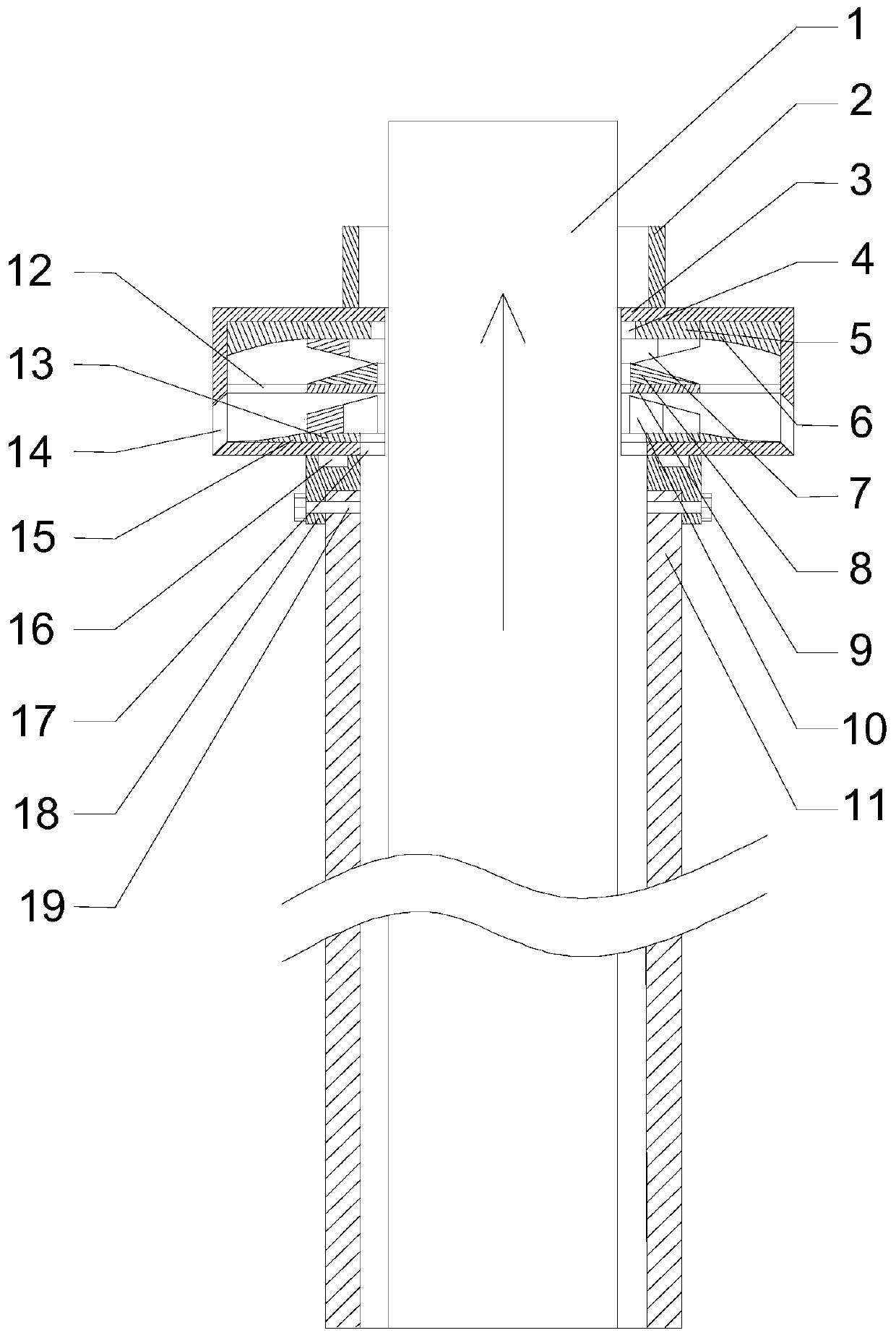
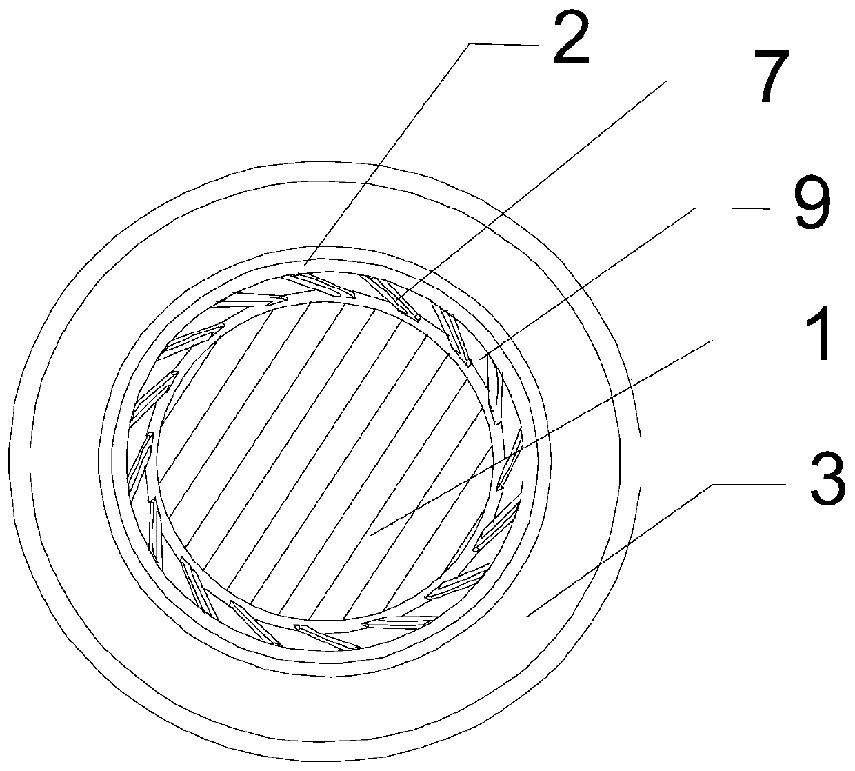
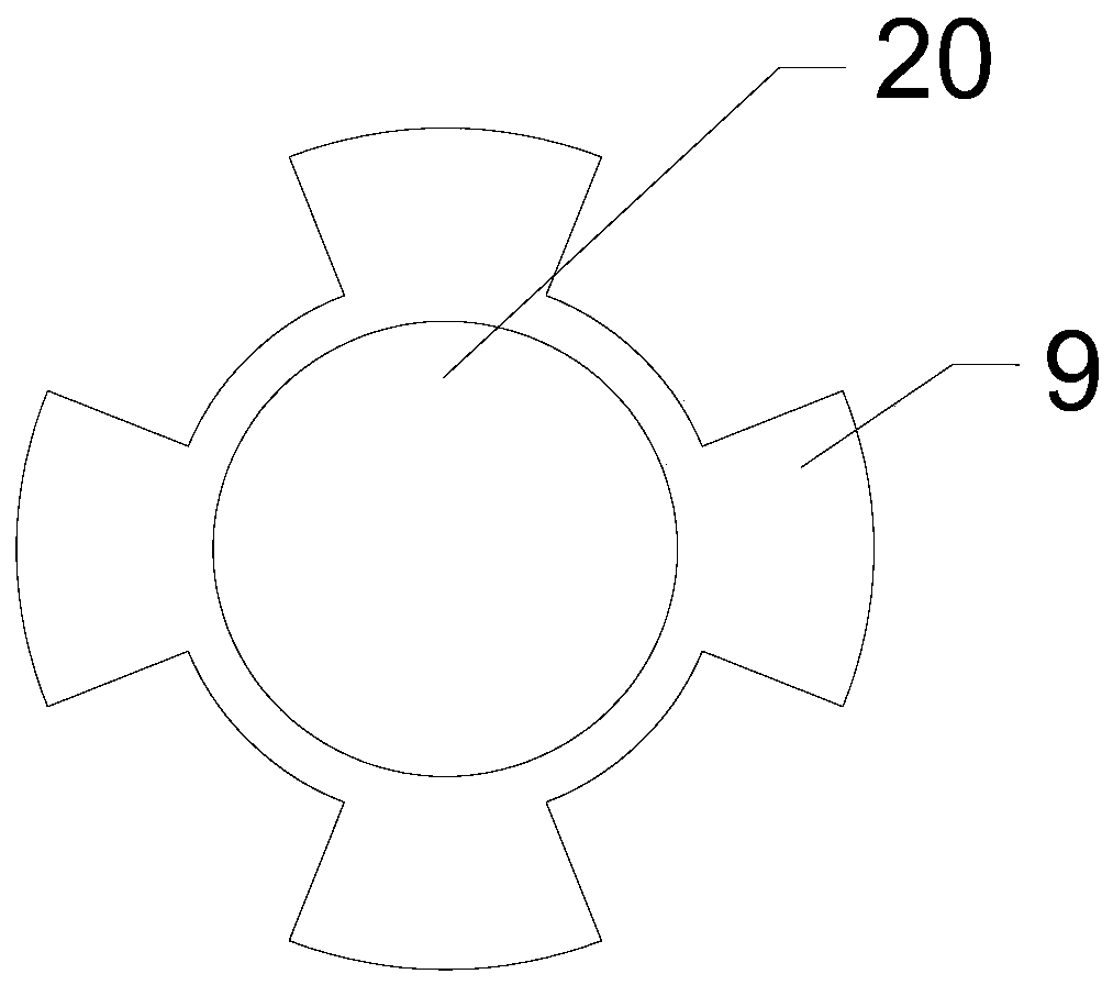
[0025] Such as Figure 1 to Figure 3 As shown, an obstacle-free cleaning device for abandoned piles includes a casing 3 arranged above the lower casing 11 of a full-automatic full-rotary drilling rig and having a cylindrical cavity inside, and an upper casing 2 is arranged on the upper surface of the casing 3 , and an upper through hole 4 communicating with the upper casing 2 is opened on the upper wall of the housing 3, and a lower through hole 17 corresponding to the upper through hole 4 is opened on the lower wall of the housing 3, and in the middle of the cavity of the housing 3 A circular support plate 9 parallel to the upper and lower surfaces of the housing 3 is fixed. In this embodiment, the edge of the support plate 9 is welded to the side surface of the inner cavity of the housing 3 by welding; the middle part of the support plate 9 has a A through hole 20 for the waste pile 1 to pass through, and a plurality of slag discharge holes 12 are evenly opened around the th...

Embodiment 2

[0029] Since the cavity of the housing 3 is cylindrical, when the upper scraper 7 cleans the attached soil on the surface of the waste pile 1, there is always a lot of soil that is thrown to the corner of the cavity and the support plate through the interval between the blades. 9 and the bottom of the cavity of the housing 3; thereby increasing the weight of the device, and at the same time because the distribution of the soil in the cavity is random, it is easy to cause the uneven quality of the housing 3, which is easy to make The device produces eccentricity during rotation, which seriously affects its stability and service life.

[0030] Therefore, the difference between this embodiment and Embodiment 1 is that an annular upper baffle plate 6 coaxial with the upper ring seat 5 is provided between the upper ring seat 5 and the inner side wall of the housing 3, and the upper baffle plate 6 The upper surface is fixed on the upper inner side wall of the housing 3, the lower su...

Embodiment 3

[0032] The difference between this embodiment and Embodiment 2 is that there is a base 18 provided between the casing 3 and the lower casing 11, a hole for the waste pile 1 to pass is opened in the middle of the base 18, and an annular concave hole is provided on the upper surface of the base 18. Groove, the lower surface of the housing 3 is provided with four sliders 16 matching the annular groove, and the four sliders 16 are all embedded in the annular groove, and the base 18 is fixedly connected with the lower sleeve 11. In this embodiment, in order to facilitate the installation and disassembly of the base 18 , fastening bolts 19 are used to connect it to the lower casing 11 .

[0033] When the housing 3 rotates under the drive of the upper casing 2, the slider 16 slides in the chute without causing the lower casing 11 to rotate. When the lower casing 11 has a tendency to tilt, the rotation of the slider 16 will The correction thereof effectively ensures the stability of t...


PUM


Abstract

The invention discloses a barrier-free cleaning device for an abandoned pile. The barrier-free cleaning device comprises a shell with a cylindrical cavity formed in the inner part, an upper sleeve tube is arranged on the upper surface of the shell, an upper through hole communicating with the sleeve tube is formed in the upper wall of the shell, a lower through hole corresponding to the upper through hole is formed in the lower wall of the shell, a round support plate is fixed to the middle of the hollow cavity of the shell, a penetrating hole for the abandoned pile to penetrate is formed in the middle of the support plate, a plurality of slag discharging holes are formed in the upper surface of the support plate in the radial direction of the support plate, an upper ring seat coaxially arranged with the upper through hole is arranged on the upper wall of the hollow cavity, a plurality of upper scraping blades are arranged on the bottom surface of the upper ring seat in the radial direction of the ring seat, a plurality of discharging holes are evenly formed in the side surface of the shell between the support plate and the lower wall of the cavity, and a lower sleeve tube is further arranged on the lower part of the shell. Soil stuck to the outer wall of the abandoned pile is cleaned by using the barrier-free cleaning device, the jacking-up weight is effectively decreased, meanwhile the labor intensity of works is relieved, and the jacking-up efficiency is improved.

Description

technical field [0001] The invention relates to the field of building construction, in particular to an obstacle-free cleaning device for abandoned piles. Background technique [0002] In recent years, my country's subway tunnel construction has entered a stage of rapid development, and the construction of subway tunnels has started in full swing. At the same time, my country's tunnel construction technology is also constantly improving, the level of tunnel construction has achieved leapfrog development, and many tunnel construction methods emerge in endlessly. The subway track constructed in the city is generally located underground in the bustling area of ​​the city. Because the traffic in these areas is relatively heavy and there are many buildings, the ground floor movement and ground subsidence are prone to occur during the construction process, which will not only affect urban traffic, It will also affect adjacent buildings, underground pipelines and other public infr...

Claims


Application Information

Patent Timeline
Patent Type & Authority Patents(China)
IPC IPC(8): E02D9/02
CPCE02D9/02
Inventor 李义政
Owner 甘肃九州岩土工程有限公司
Learn More