Light capturing particle control device and method

A control device and light capture technology, applied in optics, optical components, and processing by applying diffraction/refraction/reflection, etc., can solve problems such as difficulty in switching between different control modes, difficulties, and lack of control capabilities for other motion modes

Pending Publication Date: 2019-09-20
UNIV OF SCI & TECH OF CHINA
View PDF5 Cites 7 Cited by
  • Summary
  • Abstract
  • Description
  • Claims
  • Application Information

AI Technical Summary

Problems solved by technology

However, in the proposed schemes, most of them emphasize the cooling of particle motion or the reduction of particle amplitude, and lack the control ability of other motion modes.
At the same time, traditional control devices are complex, expensive, difficult to debug, and difficult to switch between different control modes

Method used


Image

  • Light capturing particle control device and method
  • Light capturing particle control device and method
  • Light capturing particle control device and method

Examples


Embodiment Construction

[0054] In order to make the purpose, features and advantages of the present invention more obvious and understandable, the technical solutions in the embodiments of the present invention will be clearly and completely described below in conjunction with the accompanying drawings in the embodiments of the present invention. Obviously, the described The embodiments are only some of the embodiments of the present invention, but not all of them. Based on the embodiments of the present invention, all other embodiments obtained by those skilled in the art without making creative efforts belong to the protection scope of the present invention.

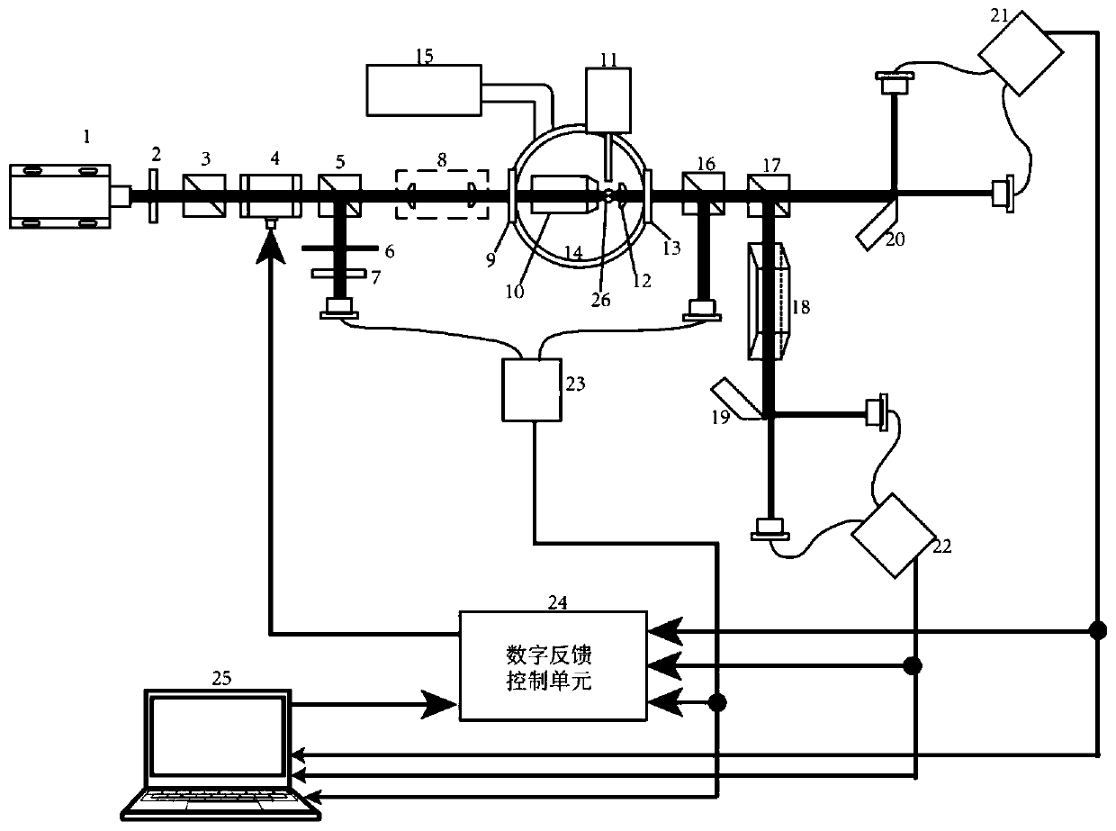
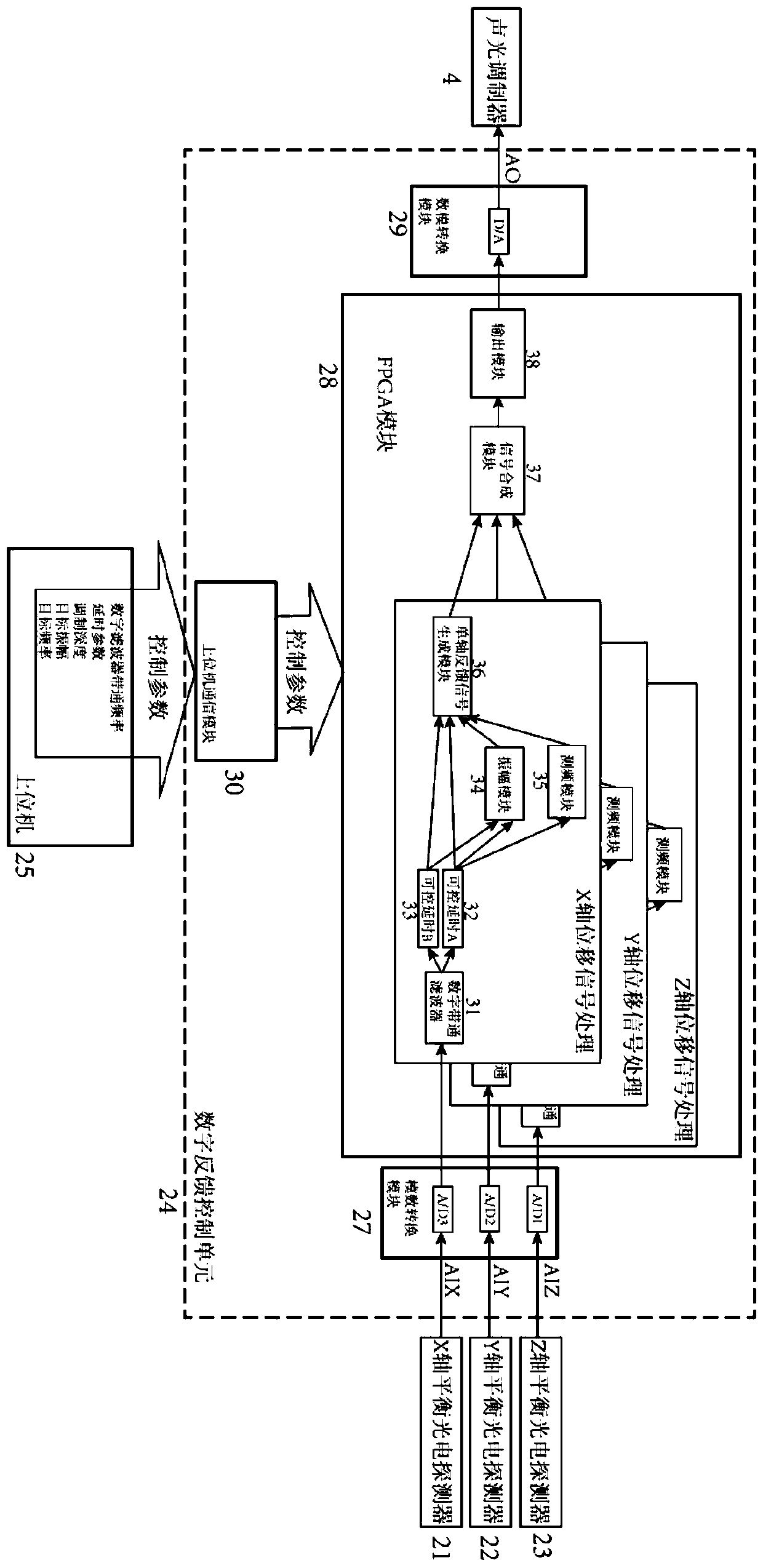
[0055] see figure 1 and figure 2 , figure 1 A schematic diagram of the structure of the light-harvesting unit in the light-harvesting particle control device provided by an embodiment of the present invention, figure 2 A schematic structural diagram of a digital feedback control unit and a host computer in a control device for light-harv...


PUM


Abstract

The invention relates to a light capturing particle control device applied to the field of photoelectric technology. The device comprises a light capturing unit, a digital feedback control unit and an upper computer. The light capturing unit is used for measuring a three-dimensional position signal of a captured micro-nano particle and transmitting the three-dimensional position signal to the digital feedback control unit and the upper computer. The upper computer is used for generating a feedback control parameter based on the three-dimensional position signal and sending the feedback control parameter to the digital feedback control unit; and the digital feedback control unit is configured to generate a feedback control signal to the light capturing unit based on the three-dimensional position signal, the feedback control parameter, and a target motion state, thereby realizing feedback controlling on the light capturing unit. In addition, the invention also discloses a light capturing particle control method, thereby realizing controlling of motion states like the vibration cooling, vibration amplitude, and vibration efficiency of light capturing particles.

Description

technical field [0001] The invention relates to the field of optoelectronic technology, in particular to a control device and method for light-harvesting particles. Background technique [0002] Optical tweezers technology or optical trapping technology, which applies a gradient force of light intensity to the center of the optical potential well by focusing a beam of light on the particles in the optical field to achieve the capture of micro-nano particles. Since the invention of optical tweezers in 1986, the technology of light trapping in liquid has been greatly developed and widely used in practice. Taking advantage of the ability of optical tweezers to control micro-nano particles, light-trapping technology is used in nanofabrication, micromechanical assembly and other fields. At the same time, because the size of the trapped particles is usually in the micron or nanometer scale, its movement is particularly susceptible to the influence of the external environment. Tak...

Claims


Application Information

Patent Timeline
Patent Type & Authority Applications(China)
IPC IPC(8): G02B21/32G21K1/06
CPCG02B21/32G21K1/06
Inventor 郑瑜孙方稳
Owner UNIV OF SCI & TECH OF CHINA
Why Eureka
Try Eureka