Display device and control method thereof

A technology of a display device and a control method, which is applied in the direction of static indicators, optics, instruments, etc., can solve the problems of low display resolution, large image loss, and low display brightness, and achieve high display resolution, small brightness loss, and solution Display low brightness effect

Active Publication Date: 2019-09-20
BOE TECH GRP CO LTD +1
View PDF8 Cites 17 Cited by
  • Summary
  • Abstract
  • Description
  • Claims
  • Application Information

AI Technical Summary

Problems solved by technology

[0005] The technical problem to be solved by the embodiments of the present invention is to provide a display device and its control method, so as to solve the problems of low display brightness, low display resolution and large picture loss in existing anti-peeping solutions.

Method used


Image

  • Display device and control method thereof
  • Display device and control method thereof
  • Display device and control method thereof

Examples


no. 1 example

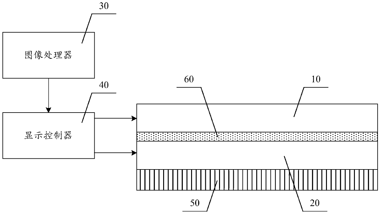
[0065] figure 2 It is a schematic structural diagram of the display device according to the first embodiment of the present invention. Such as figure 2 As shown, the main structure of the display device includes an image processor 30 and a display controller 40 , and also includes a backlight module 50 , a grating panel 20 , an adhesive layer 60 and a display panel 10 stacked in sequence toward the user's viewing direction. Wherein, the adhesive layer 60 is disposed between the display panel 10 and the grating panel 20 , and the display panel 10 is glued on the light emitting surface of the grating panel 20 through the adhesive layer 60 , so that the display panel 10 and the grating panel 20 are glued together. In this embodiment, there is a certain vertical distance between the pixel units of the double-layer panel, which generally includes the thickness of the lower substrate of the display panel, the thickness of the upper substrate of the grating panel and the thickness...

no. 2 example

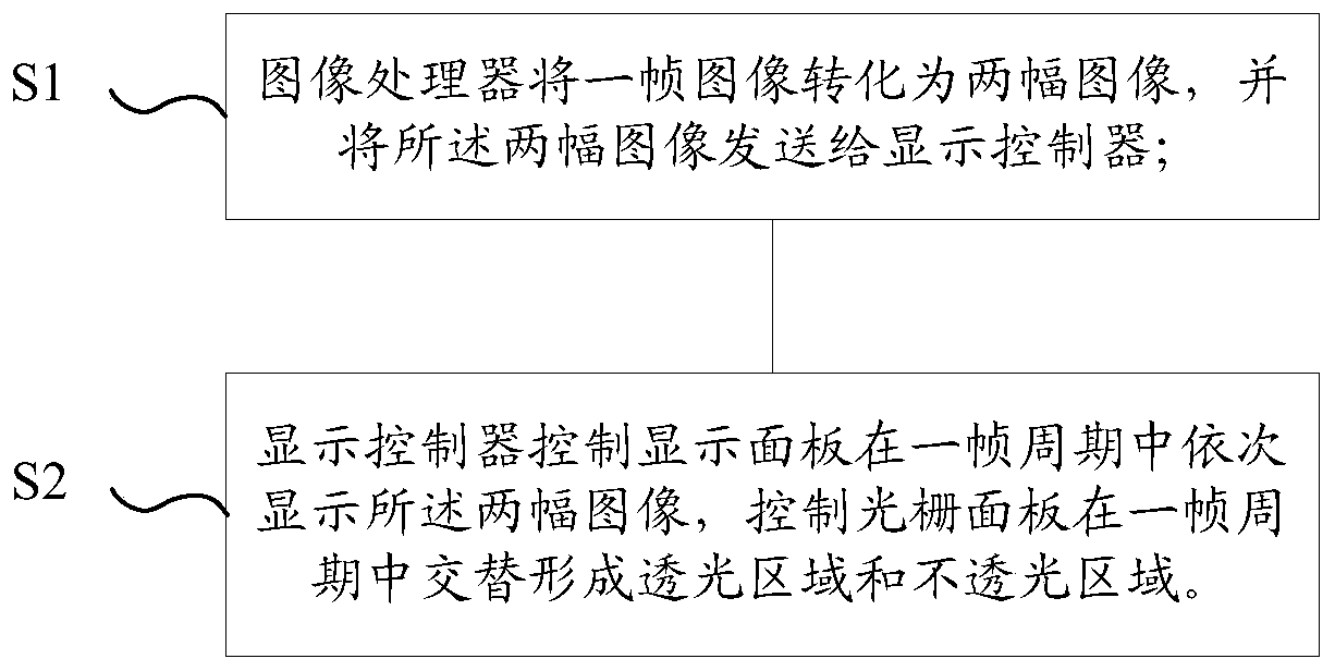
[0094] This embodiment is an extension of the aforementioned first embodiment. The control method of the display device in this embodiment includes:

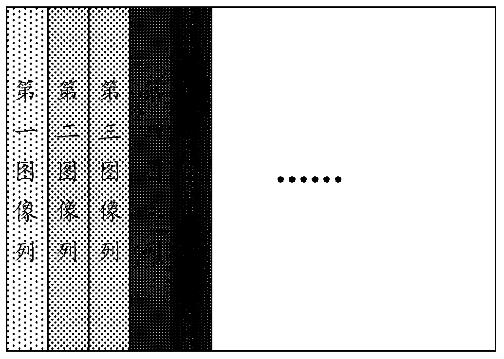
[0095] S21. The image processor receives the original image data, and divides a frame of image into N image columns according to the column direction, where N is a positive integer greater than or equal to 2;

[0096] S22. The image processor generates a first image and a second image according to the N image columns, and generates brightness information of each image column according to the N image columns, and each image includes N data columns;

[0097] S23. The image processor sends the first image, the second image and brightness information to the display controller;

[0098] S24. The display controller generates a first grating driving signal and a second grating driving signal according to the first image and the second image respectively, and generates a first brightness driving signal and a second brightness driving s...

no. 3 example

[0104] Figure 8 It is a schematic structural diagram of a display device according to the third embodiment of the present invention. This embodiment is an extension of the aforementioned first and second embodiments. The main structure of the display device of this embodiment is basically the same as that of the aforementioned first and second embodiments, including a display panel 10, a grating panel 20, an image The difference between the processor 30, the display controller 40, the backlight module 50 and the bonding layer 60 is that the display device of this embodiment further includes a grating adjustment device. Such as Figure 8 As shown, the grating adjustment device 70 is connected to the display controller 40, and is used to obtain the user's position information, and send the user's position information to the display controller 40, so that the display controller 40 controls the grating panel 20 to adjust the position of the grating array. .

[0105] The contro...


PUM


Abstract

The embodiment of the invention provides a display device and a control method thereof. The control method of the display device comprises the steps that an image processor divides a frame of image into M images and sends the M images to a display controller, wherein the M is an even number larger than or equal to 2; and the display controller controls the display panel to sequentially display the M images in a frame period, and controls the grating panel to sequentially form grating patterns corresponding to the M images in the frame period. The invention discloses a double-layer panel structure based on a grating panel and a display panel. A frame of image is displayed in multiple times in a frame period, and grating patterns corresponding to the images displayed for multiple times are formed in sequence through time-sharing control, peep-proof display is achieved, switching between the peep-proof display mode and the shared display mode is achieved, and the display device has the advantages of being small in brightness loss, high in display resolution ratio, free of loss of peep-proof display state images and the like.

Description

technical field [0001] The present invention relates to the field of display technology, in particular to a display device and a control method thereof. Background technique [0002] With the continuous development of display technology, people have more and more diverse demands on display methods, and at the same time, users have a stronger awareness of personal privacy protection, and more and more scenarios require display devices to have anti-peeping functions. For example, in the field of business display, there are display requirements such as portability, privacy protection, and high color gamut and high contrast. Therefore, privacy protection technology has become an important content of high-end business notebooks as a privacy protection method. [0003] At present, in order to satisfy the anti-peeping function, various solutions have been proposed in related technologies. The inventors of the present application have found through research that these solutions all...

Claims


Application Information

Patent Timeline
Patent Type & Authority Applications(China)
IPC IPC(8): G09G3/36G09G3/3208
CPCG09G3/36G09G3/3208G09G2354/00G09G2358/00G09G2320/028G09G2300/023G09G3/3648G09G3/3225H04N2013/403H04N13/31G02F1/1323G02F1/133528G02F1/137G02F2201/30G02F2201/44G02F2202/28G09G2320/0626G09G2320/068H10K59/50
Inventor 陈寅伟孙海威
Owner BOE TECH GRP CO LTD
Why Eureka
Try Eureka