Supercharge Your Innovation With Domain-Expert AI Agents!

A foam cable, injection mold, foam extruder and production process

A technology of injection mold and extruder, which is applied in the field of injection mold, foam extruder and production process, and foamed cable, can solve problems such as affecting the bending performance of cables, and achieve the effect of enhancing bending performance

Active Publication Date: 2020-10-09
杭州宏峰电缆有限公司
View PDF9 Cites 0 Cited by
  • Summary
  • Abstract
  • Description
  • Claims
  • Application Information

AI Technical Summary

Problems solved by technology

[0004] The above-mentioned prior art solution has the following defects: in order to protect the internal conductive core of the high-foaming coaxial cable, a thicker foam insulating layer is provided on the outside of the conductive core for protection, and the thicker The foam insulation layer will not break due to a little abrasion and expose the conductive core, but it will also affect the bending performance of the cable

Method used


Image

  • A foam cable, injection mold, foam extruder and production process
  • A foam cable, injection mold, foam extruder and production process
  • A foam cable, injection mold, foam extruder and production process

Examples


Embodiment 1

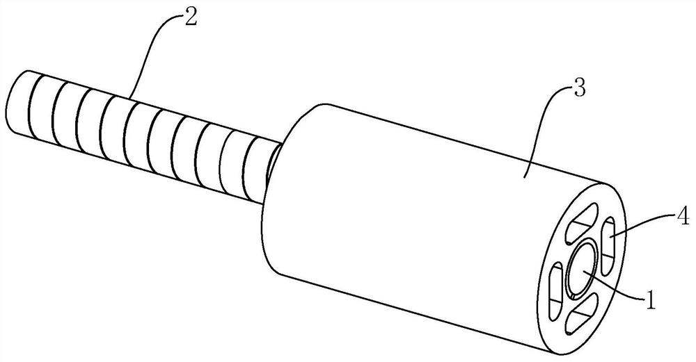
[0052] like figure 1 As shown, a foamed cable includes a conductive wire core 1 , a mica tape 2 coated on the outer side of the conductive wire core 1 , and a foamed insulating layer 3 coated on the outer side of the mica tape 2 .

[0053] like figure 1 As shown, the mica tape 2 is wrapped on the outer side of the conductive wire core 1 in a spiral structure, and the edge of the mica tape 2 covered after is covered on the mica tape 2 wrapped in the previous circle to form a dense fire-resistant insulating structure.

[0054] like figure 1 As shown, the foamed insulating layer 3 is made of foamed PE, and the inside of the foamed insulating layer 3 is formed with four inner holes 4 along the length direction of the cable. Observed from the cable section, the cross-section of the inner holes 4 is elliptical and along the length of the cable. The conductive wire cores 1 are evenly distributed in the circumferential direction. The inner hole 4 saves the material used for foaming...

Embodiment 2

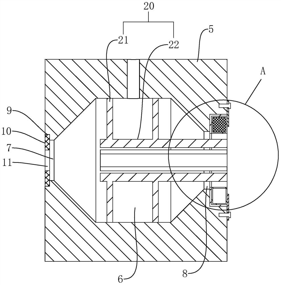
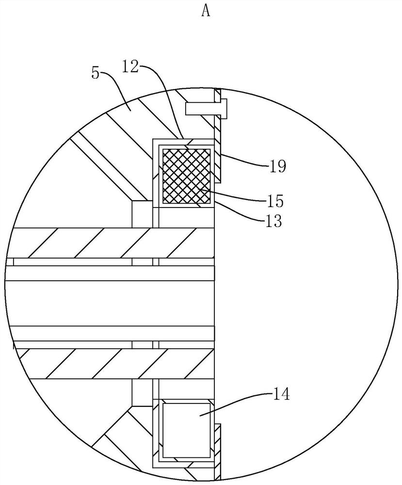
[0056] like figure 2As shown, an injection mold for the foamed cable described in the first embodiment includes a mold body 5, and an extrusion cavity 6 is formed inside the mold body 5, and the two ends of the extrusion cavity 6 penetrate through to form a cavity inlet 7 and the outlet port 8. The side surface of the mold body 5 is formed with a feed port that communicates with the extrusion cavity 6 , and the foaming injection molding machine transports the foamed PE into the extrusion cavity 6 . The conductive wire core 1 enters the extrusion cavity 6 through the cavity inlet 7 , the conductive wire core 1 enters the extrusion cavity 6 and then the foamed PE wraps the outer side of the conductive wire core 1 , and then is transported out from the cavity outlet 8 .

[0057] like figure 2 As shown, the end face of the mold body 5 with the cavity inlet 7 is formed with a sealing groove 9, and a sealing ring 10 is embedded in the sealing groove 9. The center of the sealing...

Embodiment 3

[0062] A foaming extruder includes an extruder body and the injection mold described in the second embodiment.


PUM


Abstract

The invention relates to the technical field of cable production, in particular to a foaming cable, an injection mould, a foaming extruder and a production process. The foaming cable has the advantage of good bending performance. The foaming cable comprises a conductive wire core and a foaming insulating layer arranged on the outer side of the conductive wire core. The foaming insulating layer is internally provided with a plurality of inner holes along the length direction of the cable, and the inner holes surround the conductive wire core. The foaming insulating layer wraps the conductive wire core to protect the conductive wire core, so that the conductive wire core will not be exposed when the foaming insulating layer is slightly worn out. At the same time, the bending performance of the cable is enhanced by arranging the inner holes along the length direction of the cable.

Description

technical field [0001] The invention relates to the technical field of cable production, in particular to a foamed cable, an injection mold, a foaming extruder and a production process. Background technique [0002] The purpose of foaming the foam cable is to make the product lightweight, strengthen the thermal insulation and turbulence of the product, and increase the threshold value of the tangent value of the dielectric loss angle. Because the polarization loss increases with the increase of frequency at high frequency, especially when the capacitor adopts polar dielectric, the polarization loss increases rapidly with the increase of frequency. It is easy to cause the capacitor insulating material to break down due to overheating, so it is necessary to maintain a small loss tangent when working. [0003] The existing invention patent with the authorization announcement number CN 101821820UB discloses a high-foaming coaxial cable. In the technical solution, in the insula...

Claims


Application Information

Patent Timeline
Patent Type & Authority Patents(China)
IPC IPC(8): H01B7/04H01B7/18H01B7/295H01B13/24
CPCH01B7/04H01B7/1845H01B7/295H01B13/24
Inventor 滕峰
Owner 杭州宏峰电缆有限公司
Features
  • R&D
  • Intellectual Property
  • Life Sciences
  • Materials
  • Tech Scout
  • Unparalleled Data Quality
  • Higher Quality Content
  • 60% Fewer Hallucinations
Learn More