Battery diaphragm having fast charging function

A diaphragm and battery technology, applied in the field of battery diaphragm, to achieve the effects of good heat resistance and puncture strength, good molding, and improved porosity

Pending Publication Date: 2019-09-20
河南曼博睿新材料科技有限公司
View PDF0 Cites 1 Cited by
  • Summary
  • Abstract
  • Description
  • Claims
  • Application Information

AI Technical Summary

Problems solved by technology

[0004] Aiming at the deficiencies of the prior art, the present invention provides a battery diaphragm with a fast chargin

Method used


Image

  • Battery diaphragm having fast charging function
  • Battery diaphragm having fast charging function

Examples


Embodiment 1

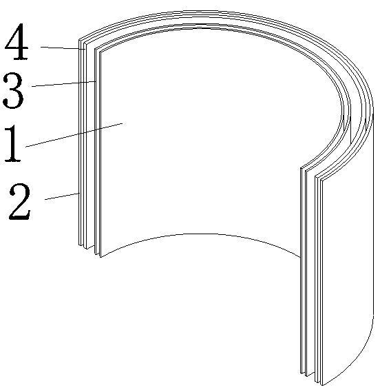
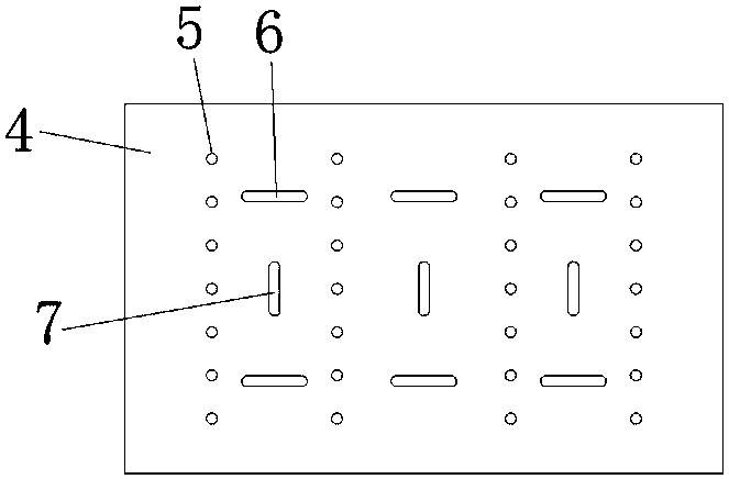
[0032] Example 1: See Figure 1-2 , a separator for a battery with a fast charging function, comprising a positive electrode 1, a negative electrode 2, a diaphragm a3 and a diaphragm b4, the diaphragm a3 and the diaphragm b4 are both arranged between the positive electrode 1 and the negative electrode 2, and the diaphragm a3 is arranged on the diaphragm b4 On the inner side, the thickness of the diaphragm a3 is half of the thickness of the diaphragm b4, and the manufacturing process and materials of the diaphragm a3 and the diaphragm b4 are the same, the diaphragm b4 is provided with holes 5, the holes 5 run through the front and back of the diaphragm b4, and the entire wall of the diaphragm b4 is provided with eight rows of holes 5 , and there are seven holes 5 vertically, and seven holes 5 are equidistantly opened, and each row of holes 5 is equidistantly opened, and the gap between each row of holes 5 is provided with two horizontal grooves 6 and one vertical groove 7, and ...

Embodiment 2

[0034] Embodiment 2: a kind of preparation method of the separator for battery with fast charge function, comprises the following steps:

[0035] S1. Preparation of mixed particles:

[0036] S1.1. Put 2 parts of cocamidopropyl amine oxide, 3 parts of lauryl amidopropyl amine oxide, 40 parts of absolute ethanol, 2 parts of ammonia water, and 100 parts of water into the reactor in corresponding parts by weight, and heat to keep The temperature in the reaction kettle was 40°C, and the mixture A was obtained after continuous stirring for 25 minutes;

[0037] S1.2. Add tetraethyl orthosilicate which is 6 times the total mass of mixture A to the reaction kettle treated in S1.1, heat to keep the temperature in the reaction kettle at 38°C, and keep stirring for 15 minutes to obtain mixture B for later use;

[0038]S1.3. Add a composite solution of 10% of the total mass of mixture B to the reactor after S1.2, then heat to keep the temperature in the reactor at 55°C, and obtain mixture...

Embodiment 3

[0043] Embodiment 3: a kind of preparation method of the separator for battery with fast charge function, comprises the following steps:

[0044] S1. Preparation of mixed particles:

[0045] S1.1. Put 4 parts of cocamidopropyl amine oxide, 6 parts of lauryl amidopropyl amine oxide, 43 parts of absolute ethanol, 3 parts of ammonia water, and 105 parts of water into the reactor in corresponding parts by weight, and heat and keep The temperature in the reaction kettle was 45°C, and the mixture A was obtained after continuous stirring for 30 minutes;

[0046] S1.2. Add tetraethyl orthosilicate which is 9 times the total mass of mixture A to the reaction kettle treated in S1.1, heat to keep the temperature in the reaction kettle at 42°C, and keep stirring for 20 minutes to obtain mixture B for later use;

[0047] S1.3. Add a composite solution of 15% of the total mass of mixture B to the reactor after S1.2, then heat to keep the temperature in the reactor at 60°C, and obtain mixtu...


PUM

PropertyMeasurementUnit
Lengthaaaaaaaaaa
Diameteraaaaaaaaaa

Abstract

The invention relates to the technical field of a battery diaphragm and discloses a battery diaphragm having a fast charging function. The battery diaphragm comprises an anode, a cathode, a diaphragm a and a diaphragm b. The diaphragm a and the diaphragm b are arranged between the anode and the cathode; the diaphragm a is arranged at the inner side of the diaphragm b; the diaphragm a and the diaphragm b are same in manufacturing process and material; and the diaphragm b is provided with holes. According to the battery diaphragm having the fast charging function, the diaphragm b is provided with horizontal grooves, vertical grooves and the holes; the horizontal grooves and the vertical grooves allow electrolyte between the anode and the cathode to flow better but not be slowed down by the diaphragm a and the diaphragm b, so that influence of normal use of the battery due to too low power can be prevented; the holes can make the flow surface of the electrolyte wider, and the electrolyte can permeate from all aspects to the diaphragm a through the holes, thereby increasing fluidity of the electrolyte between the diaphragm a and the diaphragm b as well as between the anode and the cathode and ensuring normal use of the battery.

Description

technical field [0001] The invention relates to the technical field of battery separators, in particular to a battery separator with fast charging function. Background technique [0002] The battery diaphragm refers to a layer of diaphragm material between the positive and negative electrodes of the battery. It is a very critical part of the battery and has a direct impact on battery safety and cost. Its main function is to isolate the positive and negative electrodes and prevent the electrons in the battery from Freely pass through, allowing the ions in the electrolyte to pass freely between the positive and negative electrodes. The ion conductivity of the battery separator is directly related to the overall performance of the battery. Under normal circumstances, it can limit the rise of the current, prevent the battery from exploding due to short circuit, and has the function of self-closing protection of micropores, which plays a role of safety protection for battery user...

Claims


Application Information

Patent Timeline
IPC IPC(8): H01M2/14H01M2/16H01M2/18
CPCH01M50/403H01M50/411H01M50/44H01M50/463Y02E60/10
Inventor 琚河同窦高峰杨永生
Owner 河南曼博睿新材料科技有限公司
Why Eureka
Try Eureka