
Industrial control system based on Internet of Things

An industrial control system and Internet of Things technology, applied in the circuit field, can solve problems such as signal error, real-time monitoring, and error

Active Publication Date: 2019-09-20
广州市研恒计算机科技有限公司
View PDF15 Cites 6 Cited by
  • Summary
  • Abstract
  • Description
  • Claims
  • Application Information

AI Technical Summary

Problems solved by technology

[0002] At present, the application of Internet of Things technology in industry mainly includes manufacturing execution system (MES), manufacturing supply chain management, production process optimization, product equipment monitoring management, environmental monitoring and energy management, safety production management and advanced manufacturing technology, etc. In one aspect, the industrial control system based on the Internet of Things mainly includes an industrial equipment power acquisition module, a control terminal, and a signal transmission module. The power acquisition module collects the operating power of industrial equipment and transmits it to the control terminal through the signal transmission module, while the power During the transmission process of the output signal of the acquisition module through the signal transmission module, there will be certain signal errors, especially due to the interference of the same frequency signal or strong magnetic field during the signal transmission process, the signal error will be greater, so that a wrong analysis can be made. Therefore, it is necessary to monitor the signal in the analog signal transmission channel in real time

Method used


Image

  • Industrial control system based on Internet of Things

Examples


Embodiment 1

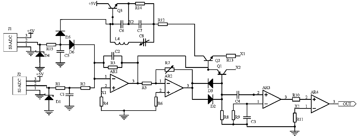
[0010] Embodiment 1, an industrial control system based on the Internet of Things, including a frequency acquisition circuit 1, a frequency acquisition circuit 2, a signal calibration circuit, and a signal output circuit, the frequency acquisition circuit 1 and the frequency acquisition circuit 2 acquire analog signal transmission channel input The signal frequency of terminal and output terminal, this analog signal transmission channel is the channel that the computer control terminal based on the Internet of Things receives the signal of power signal acquisition module, and the signal calibration circuit uses operational amplifier AR1, operational amplifier AR2 and variable resistor R7 The composed voltage stabilization circuit stabilizes the signal potential, the frequency acquisition circuit 1 outputs the signal potential, and at the same time, the limiter circuit composed of diode D2 and diode D3 is used to limit the signal, and the output signal of the frequency acquisitio...

Embodiment 2

[0013] Embodiment 2. On the basis of Embodiment 1, the signal output circuit uses operational amplifier AR3, operational amplifier AR4, capacitor C3, and capacitor C4 to form a composite circuit to filter out disturbance signal noise and then output it, that is, it is an object-based The error correction signal of the control terminal of the networked industrial control system, the non-inverting input terminal of the operational amplifier AR3 is connected to one end of the capacitor C4, the inverting input terminal of the operational amplifier AR3 is connected to the resistor R9 and one end of the capacitor C3, and the other end of the capacitor C4 is connected to One end of the resistor R8 and the base of the transistor Q1, the output terminal of the operational amplifier AR3 is connected to one end of the resistor R10, the other end of the resistor R10 is connected to the non-inverting input terminal of the operational amplifier AR4, and the inverting input terminal of the ope...

Embodiment 3

[0014] Embodiment 3, on the basis of Embodiment 1, the frequency acquisition circuit 1 and the frequency acquisition circuit 2 select the frequency acquisition device J1 and the frequency acquisition device J2 whose model is SJ-ADC to collect signals at the input and output ends of the analog signal transmission channel Frequency, the power supply terminal of the frequency collector J1 is connected to the power supply +5V, the ground terminal of the frequency collector J1 is grounded, the output terminal of the frequency collector J1 is connected to the negative pole of the voltage regulator tube D1 and one end of the resistor R1, and the positive pole of the voltage regulator tube D1 is grounded. The other end of the resistor R1 is connected to one end of the capacitor C1 and one end of the resistor R2, the other end of the capacitor C1 is grounded, and the other end of the resistor R2 is connected to the inverting input end of the operational amplifier AR1; the power terminal ...


PUM


Abstract

The invention discloses an industrial control system based on the Internet of Things. The system comprises a frequency acquisition circuit 1, a frequency acquisition circuit 2, a signal calibration circuit and a signal output circuit, the frequency acquisition circuit 1 and the frequency acquisition circuit 2 acquire signal frequencies of an input end and an output end of an analog signal transmission channel. According to the signal calibration circuit, a voltage stabilizing circuit composed of an operational amplifier AR1, an operational amplifier AR2 and a variable resistor R7 is used for stabilizing the signal potential, a frequency acquisition circuit 1 outputs the signal potential, and the frequency acquisition circuit 2 outputs a signal to pass through an inductor L4, a triode Q3 and a capacitor C6-capacitor C8 to form a frequency modulation circuit to perform frequency modulation on the signal; finally, a triode Q1 and a triode Q2 are used for forming a switching circuit; and the signal output circuit uses a composite circuit composed of an operational amplifier AR3, an operational amplifier AR4, a capacitor C3 and a capacitor C4 to filter disturbance signal noise and then outputs the disturbance signal noise, namely the error correction signal of the industrial control system control terminal based on the Internet of Things, so that the accuracy of the error correction signal is ensured.

Description

technical field [0001] The invention relates to the field of circuit technology, in particular to an industrial control system based on the Internet of Things. Background technique [0002] At present, the application of Internet of Things technology in industry mainly includes manufacturing execution system (MES), manufacturing supply chain management, production process optimization, product equipment monitoring management, environmental monitoring and energy management, safety production management and advanced manufacturing technology, etc. In one aspect, the industrial control system based on the Internet of Things mainly includes an industrial equipment power acquisition module, a control terminal, and a signal transmission module. The power acquisition module collects the operating power of industrial equipment and transmits it to the control terminal through the signal transmission module, while the power During the transmission process of the output signal of the ac...

Claims


Application Information

Patent Timeline
IPC IPC(8): H03K5/08H03D7/00H03K17/56H03H11/04G05B19/042
CPCG05B19/0423H03D7/00H03H11/04H03K5/08H03K17/56
Inventor 孙建延陈良许春香王继东
Owner 广州市研恒计算机科技有限公司
Learn More