Reciprocating shearing type straw rubbing filament and kneading machine

A shearing, straw technology, used in cutting equipment, agricultural machinery and implements, food science, etc., can solve the problems of inability to cut, jam, straw winding, etc., and achieve the effect of improving palatability

Pending Publication Date: 2019-09-27
符必成
View PDF1 Cites 0 Cited by
  • Summary
  • Abstract
  • Description
  • Claims
  • Application Information

AI Technical Summary

Problems solved by technology

[0005] The rotor assembly and the cutting blade roller of the above two shearing devices with similar structures adopt a single-direction 360-degree rotation mode, and the long and thick straw that cannot be cut off is driven by the hammer or the blade, and is wound around in the direction of rotation. On the rotor assembly and the cutting blade roller, the hammer blade or the blade is surrounded by straw and forms an integral body with the rotor and loses its effect; the rotor is locked due to the huge frictional resistance generated by the straw winding and accumulation to a certain extent with the fixed knife or rack on the inner wall of the working chamber. move, causing the machine to jam
[0006] The fence-type straw kneading machine solves the problem of straw winding around the cutting blade roller through the fence assembly with the function of fixed knife and combing function, but all the cut straw needs to be filtered out through the gap screen formed by the fence assembly. The melting and kneading effects are excellent, but the slender filaments formed in it will continue to hang on the edges of the fixed knives in the fence assembly. Since the cutting blade roller rotates and cuts in 360 degrees in one direction, the moving knife When passing through the gap, it cannot be cut or discharged, so that the gap is gradually narrowed due to the occupation of filaments, and the subsequent material continues to accumulate and cannot be removed in time. When the gap is completely blocked, the moving blade is unable to overcome its strong resistance to pass through, resulting in jamming. machine

Method used


Image

  • Reciprocating shearing type straw rubbing filament and kneading machine
  • Reciprocating shearing type straw rubbing filament and kneading machine
  • Reciprocating shearing type straw rubbing filament and kneading machine

Examples


Embodiment 1

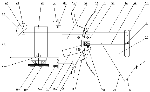
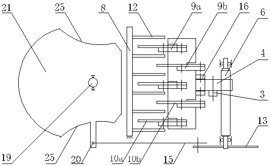
[0035] like figure 1 , figure 2 As shown, the reciprocating shearing straw kneading machine shown in this embodiment includes a machine base 1 and a feeding swing mechanism, a feeding mechanism, a shearing kneading mechanism, and a crank rocker mechanism installed on the machine base.

[0036] Feed swing mechanism

[0037] like figure 1 , figure 2 As shown, the feed swing mechanism includes an offset drive mechanism and a swing trough.

[0038] The offset driving mechanism is composed of the pendulum shaft 6 installed on the bearing, the driving rocker plate 13, and the push-pull rod 15. There is a keyway hole in the center of the driving rocker plate 13, which is sleeved on the shaft end of the pendulum shaft 6, and is fixedly connected with the pendulum shaft 6 through a flat key and an axle nut.

[0039] The swinging chute is composed of a feed chute bottom plate 21, two symmetrical pusher plates 25, a swinging trough shaft 19, a bearing 18, and a connecting sleeve 2...

Embodiment 2

[0062] like Figure 5 As shown, the reciprocating shearing straw kneading machine shown in this embodiment includes a feeding swing mechanism, a shearing kneading mechanism and a crank rocker mechanism installed on the machine base 1 .

[0063] Feed swing mechanism

[0064] Two forms of feeding swing mechanism:

[0065] (1), if Figure 5 As shown, it is made up of a swing shaft 6, a driving rocker plate 13, a push-pull rod 15 and a swing trough. The pendulum chute is made up of feed chute bottom plate 21, left and right pushing plates 25 fixed on both sides of feed chute bottom plate 21, slider 27 and linear slide rail 28 fixed on machine base 1, wherein the top of slider 27 is fixed on The bottom of the feeding trough bottom plate 21 is integrated, the slide block 27 is placed in the slide rail 28, the push-pull rod 15 is respectively hinged with the driving rocker plate 13 and one side of the feeding trough bottom plate 21, and the swinging chute performs reciprocating li...

Embodiment 3

[0076] The reciprocating shearing straw kneading machine shown in this embodiment includes a machine base and a feeding swing mechanism, a shearing kneading mechanism and a crank slider mechanism installed on the machine base.

[0077] Feed swing mechanism

[0078] Two forms of feeding swing mechanism:

[0079] (1) if Figure 7 As shown, it is a rotary feeding swing mechanism. The crank 2, the crank 30, the feed trough bottom plate 21 and the pushing plate 25 form a swing trough, and the swing trough and the connecting rod 31 are connected as one to form a double crank mechanism. The material swinging chute is placed in the outer position of the feeding port 7. When the active crank 2 is working, the swinging chute can rotate without a fixed center, forcing the internal materials to shift.


PUM


Abstract

The invention relates to a processing mechanical device for longitudinal shearing, filament and kneading of coarse straight straw such as corn and pennisetum hydridum. The processing mechanical device is a reciprocating shearing type straw rubbing machine and includes a feeding swing mechanism, a shearing rubbing mechanism and a moving cutter driving mechanism. The feeding swing mechanism includes a skewing driving mechanism and a swinging trough, and the skewing driving mechanism drives the swinging trough to move; the shearing rubbing mechanism is composed of a moving cutter component and a fixed cutter component, the moving cutter component is driven by the moving cutter driving mechanism to do reciprocating motion and cooperate with the fixed cutter component and the swinging trough, straw materials are merged in a shearing zone to complete filament and kneading, the processed straw materials can form high-quality soft filaments, and the palatability of livestock straw feed is greatly improved.

Description

[0001] Technical field [0002] The invention belongs to the technical field of agricultural machinery, and relates to a feed processing mechanical device which longitudinally cuts thick and straight crop straws such as corn straws and emperor bamboo grass, and forms them into a flexible silk shape. Background technique [0003] The currently known straw kneading machine, such as the straw kneading machine (CN02281448), uses the hammer blade on the rotor assembly to cooperate with the fixed knife to cut the straw longitudinally; The cutting blade roller is used to cooperate with multiple fence components to cut the straw longitudinally. The structures of the two methods are that the hammers or blades are arranged at intervals along the axial direction of the rotor, and the shearing is carried out in cooperation with the fixed knife. The straw is input and sheared along the radial direction of the rotor, and the straw silk cannot be achieved at one time to achieve the desired ...

Claims


Application Information

Patent Timeline
Patent Type & Authority Applications(China)
IPC IPC(8): A01F29/08A01F29/09A01F29/10A23N17/00
CPCA01F29/08A01F29/09A01F29/10A23N17/00
Inventor 符必成
Owner 符必成
Why Eureka
Try Eureka