Longitudinal-bending composite ultrasonic vibration degumming method and device based on catenary linear cutter

A composite ultrasonic and tool technology, applied in cleaning methods and utensils, chemical instruments and methods, and fluids using vibration, can solve the problems of difficult cleaning of chemical liquid on the surface of workpieces, rough processing surfaces, and lack of adjustability. The effect of promotion and implementation, high feed accuracy and small footprint

Active Publication Date: 2019-09-27
HENAN POLYTECHNIC UNIV
View PDF6 Cites 3 Cited by
  • Summary
  • Abstract
  • Description
  • Claims
  • Application Information

AI Technical Summary

Problems solved by technology

At present, most of the methods for removing hard colloids on glass plates, acrylic plates and other plates use chemical agents to remove them, which will cause environmental pollution, waste liquid treatment, and difficulty in cleaning residual liquid on the surface of the workpiece.
The shear stress of traditional mechanical processing is large, and the processed surface obtained is very rough, and it is easy to scratch the surface of the workpiece
Since the shearing force when removing the colloid has a great relationship with the angle of the tool, the angle-adjustable tool is also very important, but the angle of the tool currently used for this processing is not adjustable

Method used


Image

  • Longitudinal-bending composite ultrasonic vibration degumming method and device based on catenary linear cutter
  • Longitudinal-bending composite ultrasonic vibration degumming method and device based on catenary linear cutter
  • Longitudinal-bending composite ultrasonic vibration degumming method and device based on catenary linear cutter

Examples


Embodiment

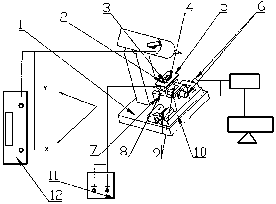
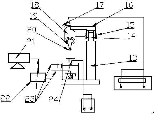
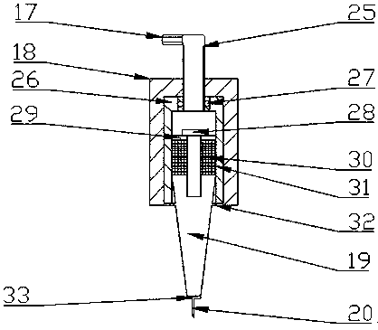
[0031] Example: see figure 1 , figure 2 and image 3 , 1-base plate, 2-plate workpiece, 3-colloid, 4-strip iron sheet, 5-working plate, 6-stepping motor, 7-X-direction slider, 8-Y-direction slider, 9-lead screw , 10-X guide rail, 11-power supply, 12-ultrasonic generator; 13-chuck support column, 14-semi-circular connector, 15-bolt, 16-F-shaped chuck, 17-rotary handle, 18- Outer sleeve, 19-conical horn, 20-catenary cutter, 21-computer, 22-drive board, 23-cable, 24-coil slot; 25-fine-tuning screw, 26-inner sleeve, 27- Bearing, 28-fastening bolt, 29-back cover, 30-piezoelectric ceramic sheet, 31-electrode sheet, 32-flange, 33-horn small end boss.

[0032] The X-direction rail 10 is fixed on the bottom plate 1, and then connected with the X-direction slider 7 through a lead screw 9, and the lead screw 9 is connected with the stepping motor 6, so as to drive the X-direction slider 7 to move on the X-direction rail 10; Then the Y-guided rail and the Y-directed slide block 8 are...


PUM


Abstract

The invention discloses a longitudinal-bending composite ultrasonic vibration degumming method and device based on a catenary linear cutter; a half-wavelength conical horn is combined with the catenary cutter, and the edge curve of the cutter adopts a catenary linear design, which can realize longitudinal and lateral bending component vibration, and form a plane elliptical cutting motion trajectory; the shearing force is small; and the notch is smooth; the horn adopts the half-wavelength conical horn, adopts an integrated design, is connected with a piezoelectric ceramic piece directly, and can realize longitudinal vibration; the working angle of the cutter can be subjected to stepless regulation by a bolt between an F-shaped chuck and a support column of the chuck, and a fine-tuning screw on the top of an outer sleeve can adjust the cutting depth of the cutter; an X-Y two-dimensional feeding table is controlled by a stepping motor; the feeding precision is high; and the micro feeding processing at any position in the X-Y plane can be realized. According to the longitudinal-bending composite ultrasonic vibration degumming method and device, the magnetic force generated by the coil is used for attracting a strip-shaped iron thin plate on a working plate to clamp a workpiece, and the advantages of convenient disassembly and installation of the workpiece, small volume and simple structure are achieved.

Description

Technical field: [0001] The invention relates to a degumming device, in particular to a method and device for degumming with longitudinal-bending composite ultrasonic vibration based on a catenary cutter. Background technique: [0002] At present, with the continuous improvement of ultrasonic vibration processing technology, better surface processing morphology can be obtained with certain processing conditions, and because this technology is periodically in contact with the workpiece, it can greatly reduce the contact between the traditional processing technology tool and the workpiece Therefore, ultrasonic vibration processing technology is more and more widely used in aerospace, automobile manufacturing, medical equipment and other fields, and many ultrasonic vibration processing methods and equipment have also been produced. At present, most of the methods for removing hard colloids on glass plates, acrylic plates and other plates use chemical agents to remove them, whic...

Claims


Application Information

Patent Timeline
Patent Type & Authority Applications(China)
IPC IPC(8): B08B7/02B08B13/00B06B1/06
CPCB08B7/028B08B13/00B06B1/06
Inventor 赵波向道辉赵重阳高国富焦锋郭星晨尹龙张致铭王晓博
Owner HENAN POLYTECHNIC UNIV
Why Eureka
Try Eureka