
Intelligent motorcycle lock

A technology for smart locks and locomotives, which is applied in the application of non-mechanical transmission-operated locks, building locks, locks, etc., can solve the problems of cumbersome installation, stolen locomotives, and high cost, and achieve improved safety performance, stable transmission, and compact structure. Effect

Pending Publication Date: 2019-09-27
浙江正东机车部件有限公司
View PDF0 Cites 1 Cited by
  • Summary
  • Abstract
  • Description
  • Claims
  • Application Information

AI Technical Summary

Problems solved by technology

Therefore, with the development of science and technology, a remote-controlled intelligent locomotive faucet lock has also appeared on the market. The locomotive faucet lock controls the rotation of the motor through the remote control circuit, and the dead bolt rotates with the motor, thereby realizing the extension or retraction of the dead bolt into the housing. , such a structure has the following disadvantages: firstly, because the existing intelligent lock for locomotives is not equipped with a structure to prevent the bolt from protruding, when locking the faucet lock, if the position of the deadbolt and the keyhole of the faucet is not completely concentric , the driving motor will still drive the deadbolt to lock hard, causing the smart locomotive lock to be prone to failure, and when this kind of smart locomotive lock is locked, the driver needs to adjust the position of the handlebar before locking it, which makes the whole locking process very cumbersome Second, when the motor drives the deadbolt to lock the locomotive, the control circuit detects that the motor is already in the locked state, but the deadbolt may not be aligned with the lock hole of the faucet lock, so it is still incompletely extended or even locked. The unextended state caused the control circuit to misjudge the position of the lock tongue, causing the faucet to fail to lock, but the user did not notice it, resulting in the locomotive being stolen; If you want to upgrade and install the locomotive smart lock, the installation will be very cumbersome and costly

Method used


Image

  • Intelligent motorcycle lock
  • Intelligent motorcycle lock
  • Intelligent motorcycle lock

Examples


Embodiment 1

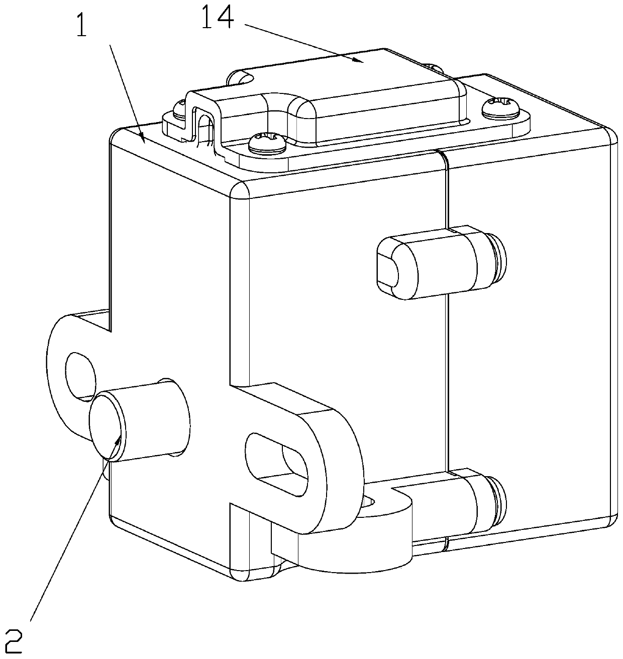
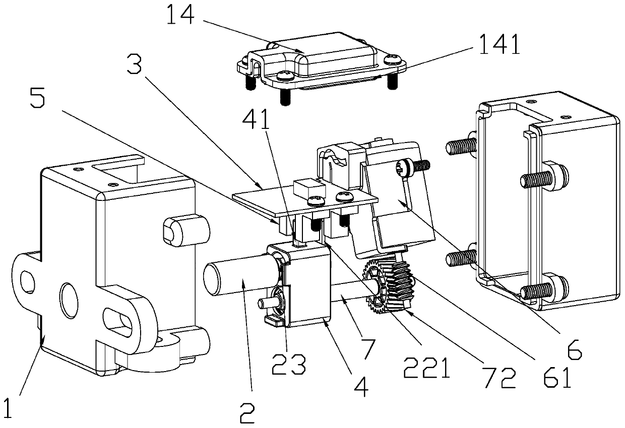
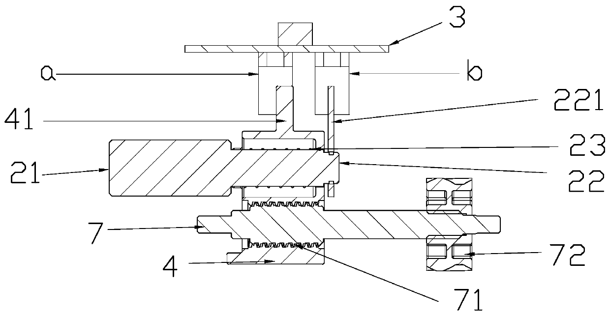
[0040] Embodiment 1: When the detection switch adopts a photoelectric switch, such as Figure 2-Figure 3 As shown, it is the locked state of the intelligent motorcycle lock of the present invention. After the intelligent motorcycle lock is installed on the locomotive (faucet lock, brake lock), the position of the deadbolt 2 of the intelligent motorcycle lock corresponds to the position of the lock hole of the leading lock. Within 1.5 meters of the locomotive, press the (lock) key on the remote control key, and after the control chip 3 receives a signal in line with the locomotive drive, the drive motor 6 will drive the worm 61 to rotate, and the worm 61 will link with the turbine 72, and then push and adjust The screw rod 7 rotates, and the adjusting screw rod 7 moves forward in conjunction with the locking sleeve 4, and the elastic member 23 abutted against the locking sleeve 4 pushes the locking end 21 of the dead bolt 2 out of the lock housing. The second detection part 221...

Embodiment 2

[0043] Embodiment 2: When the detection switch adopts a Hall switch, since the Hall element is a magnetic sensitive element, the switch made of the Hall element is called a Hall switch. When a magnetic object moves close to the Hall switch, the Hall element on the detection surface of the switch will cause the state of the internal circuit of the switch to change due to the Hall effect, thereby identifying the presence of a magnetic object nearby, and then controlling the switch to be turned on or off. The detection object of this proximity switch must be a magnetic object. When the first detection part 41 and the second detection part 221 are magnetic, the drive motor 6 drives the adjustment screw 7 to rotate, and the adjustment screw 7 will also drive the locking sleeve to move back and forth, thereby Move the first detection part 41 and the second detection part 221 or stay in the detection area of ​​the Hall element, and then generate electromagnetic induction, and the indu...

Embodiment 3

[0044] Embodiment 3: When the detection switch adopts a contact switch, because the contact switch has the specificity of the stable point of the detection method, the driving motor 6 drives the adjustment screw 7 to rotate, and the adjustment screw 7 will also drive the lock sleeve to move back and forth, thereby moving the first The detection part 41 or the second detection part 221 rests on the contact switch, presses the first detection area a (first switch contact) or the second detection area b (second switch contact) of the contact switch, and touches Click the switch to transmit the switch signal to the control chip, and then determine the current state of the motorcycle smart lock, and determine whether it is an alarm.

[0045] The intelligent locomotive lock of the present invention can also be used as the ignition system of the locomotive after the ignition switch is installed, and the above-mentioned functions such as locking, unlocking, and ignition can be realized...


PUM


Abstract

The invention relates to an intelligent motorcycle lock which comprises a lock case, a spring bolt, a driving assembly and a control chip. One end of the spring bolt serves as a locking end, and the other end of the spring bolt serves as a limiting end. The spring bolt is sleeved with a locking sleeve. The locking end is movable inside the locking sleeve. The limiting end pushes against the locking sleeve in a limited mode. The sp[ring bolt is further sleeved with an elastic piece. One end of the elastic piece pushes against the locking end, and the other end of the elastic piece pushes against the locking sleeve. The locking sleeve is connected with the driving assembly. The driving assembly drives the locking sleeve to move forwards and backwards so that the spring bolt can be telescopic inside the spring bolt. The intelligent motorcycle lock has the beneficial effects that by arranging the locking sleeve and the elastic piece, an intelligent locking function of the intelligent motorcycle lock is achieved, locking is more convenient, by arranging a detection switch, alarming and locking reminding functions of the intelligent motorcycle lock are achieved, by simplifying the parts and components, the overall size of the intelligent motorcycle lock is smaller, and installation is more convenient and faster.

Description

technical field [0001] The invention relates to the field of locks for locomotives, in particular to an intelligent lock for locomotives. Background technique [0002] General locomotives (motorcycles, battery cars) are equipped with faucet locks. When the locomotive is parked, the faucet of the locomotive is killed, and the tongue of the locomotive faucet lock extends out and enters the lock hole on the faucet to realize the locking of the direction of the faucet. , to improve the anti-theft performance of the vehicle. [0003] Locomotive faucet locks all have retractable bolts. The most traditional motorcycle faucet locks are purely mechanical, that is, the key is used to turn the lock cylinder to realize the expansion and contraction of the bolt. Such a structure is troublesome to operate and of a lower grade. Therefore, with the development of science and technology, a remote-controlled intelligent locomotive faucet lock has also appeared on the market. The locomotive f...

Claims


Application Information

Patent Timeline
Patent Type & Authority Applications(China)
IPC IPC(8): B62H5/04B62H5/18E05B49/00E05B47/02E05B41/00E05B15/10E05B15/00E05B17/22G07C9/00
CPCB62H5/04B62H5/18E05B49/00E05B47/0012E05B47/026E05B41/00E05B17/22E05B15/101E05B15/00G07C9/00174G07C9/00896E05B2047/0018E05B2047/0067
Inventor 王芳石雁赵波
Owner 浙江正东机车部件有限公司
Learn More