
Thermodynamic exhaust system adopting tangential centrifugal injection

An exhaust system and centrifugal jet technology, which is applied to the propulsion system device of space navigation aircraft, space navigation equipment, space navigation aircraft and other directions, can solve the problem of poor heat stratification elimination effect of storage tanks and poor pressure control effect of storage tanks. , weak heat and mass transfer ability, etc., to achieve the effect of technical ease, uniform temperature field, and enhanced heat and mass transfer ability

Inactive Publication Date: 2019-09-27
XI AN JIAOTONG UNIV
View PDF5 Cites 1 Cited by
  • Summary
  • Abstract
  • Description
  • Claims
  • Application Information

AI Technical Summary

Problems solved by technology

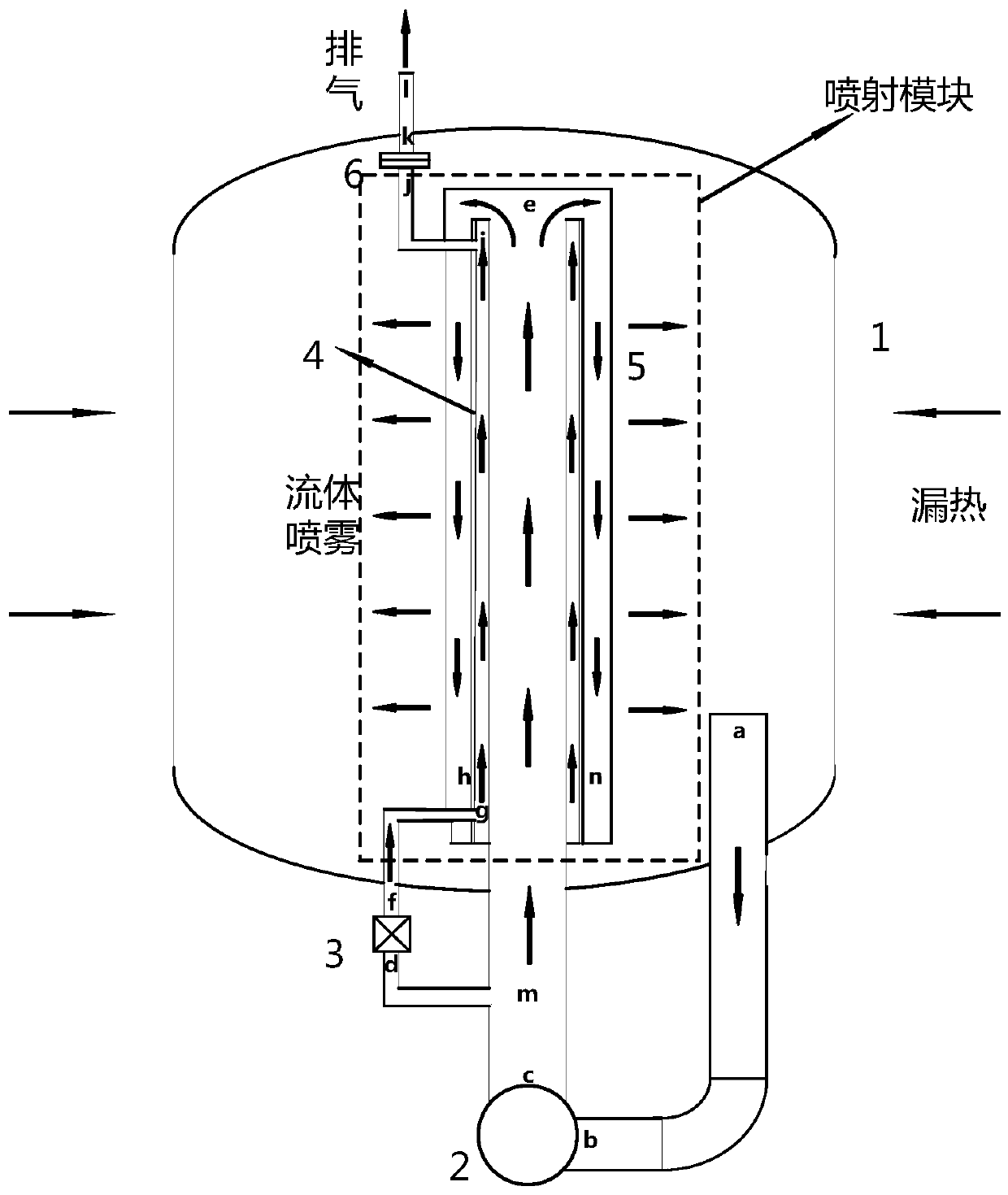
However, through research and comparison, it is found that the traditional TVS system still has the following disadvantages: centered on the axis of the tank, the spray rods are arranged in four symmetrical directions in the form of radial drilling, and after the fluid is ejected radially, its kinetic energy will be reduced. Gradually dissipate along the radial direction by virtue of the fluid's own viscosity
Due to the symmetrical injection in four directions, the main fluid in the storage tank remains still, resulting in a strong heat and mass exchange capacity only between the radial fluids in the storage tank during the spraying and diffusion process, while the mixing and agitation between the fluids along the circumferential direction is relatively strong. The ability is poor, so that the thermal stratification elimination effect of the storage tank is poor, and the heat and mass transfer ability is weak, resulting in poor pressure control effect of the storage tank

Method used


Image

  • Thermodynamic exhaust system adopting tangential centrifugal injection
  • Thermodynamic exhaust system adopting tangential centrifugal injection
  • Thermodynamic exhaust system adopting tangential centrifugal injection

Examples


Embodiment Construction

[0013] The technical solutions of the present invention will be further described below in conjunction with the drawings and embodiments.

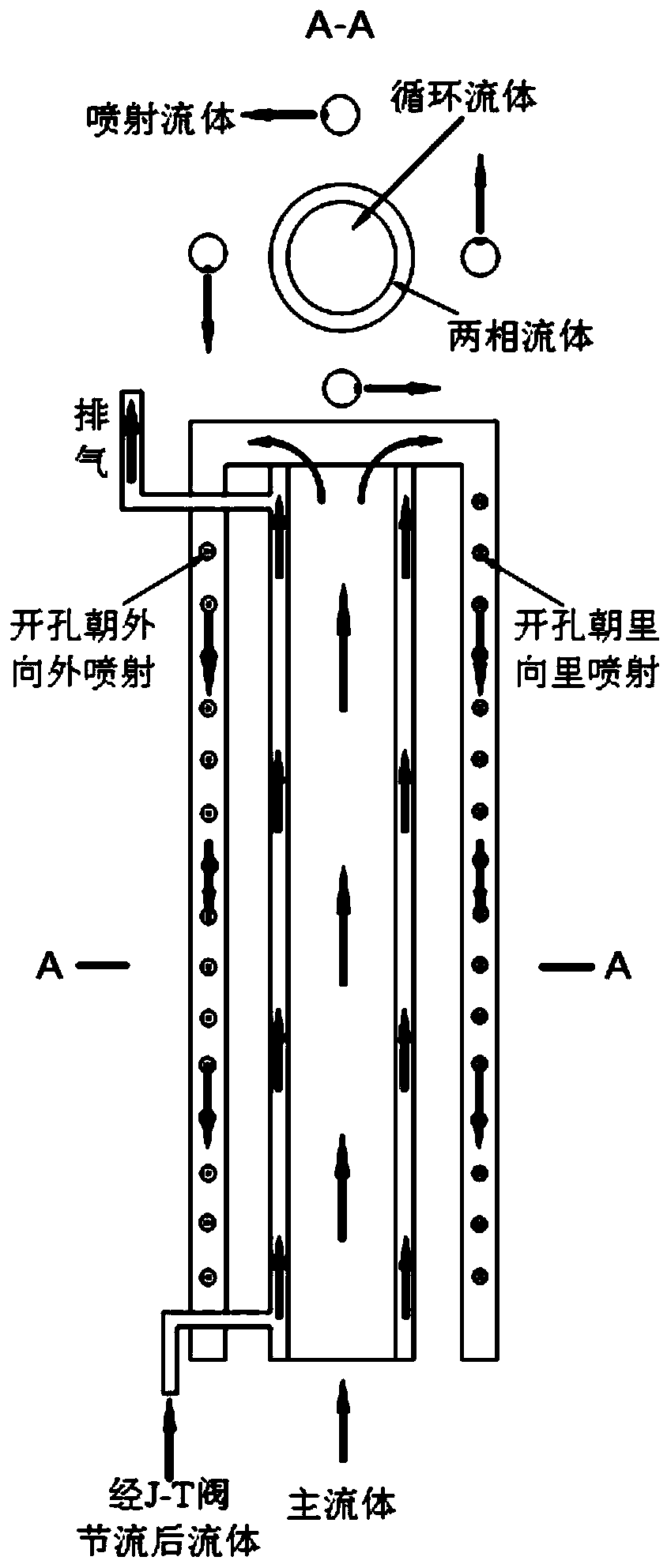
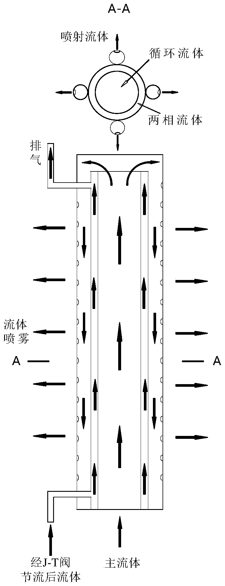
[0014] refer to figure 1 with figure 2 , a thermodynamic exhaust system using tangential centrifugal injection, including a low-temperature propellant storage tank 1, the low-temperature propellant in the low-temperature propellant storage tank 1 is immersed in the a-end of the pipeline ab, and the b-end of the pipeline ab is connected to the circulation pump 2 The inlet is connected; the outlet of the circulation pump 2 is connected to the c-end of the pipeline cm, and the m-end of the pipeline cm is divided into two streams, that is, the pipeline md and the pipeline me, and the e-end of the pipeline me is the inner casing type replacement of the low-temperature propellant storage tank 1 The top end of the inner pipe of the heater 4, the d end of the pipe md is connected to the inlet of the throttle valve 3, the outlet of the throttle v...


PUM


Abstract

The invention relates to a thermodynamic exhaust system adopting tangential centrifugal injection, and the system comprises a tangential injection pipeline in a low-temperature propellant storage tank, wherein the tangential injection pipeline is of a metal porous structure, the direction of an injection orifice is in the radial direction of the axis of the low-temperature propellant storage tank, a low-temperature propellant in the tangential injection pipeline is injected into the low-temperature propellant storage tank through the injection orifice, so that the injected low-temperature propellant is tangentially ejected relative to the axis of the low-temperature propellant storage tank to generate centrifugal force to drive a main fluid of the low-temperature propellant in the low-temperature propellant storage tank to move; the low-temperature propellant with low temperature injected by the tangential injection pipeline exchanges heat with the low-temperature propellant with high temperature in the low-temperature propellant storage tank, so that the pressure and the temperature in the low-temperature propellant storage tank are reduced, and in addition, the tangentially arranged injection orifices enable the injected low-temperature propellant to have stronger disturbing effect on main fluid in the low-temperature propellant storage tank, so that the heat exchange is stronger; and the thermodynamic exhaust system adopting tangential centrifugal injection realizes the rapid pressure reduction of the low-temperature propellant storage tank and the reduction of energy consumption.

Description

technical field [0001] The invention relates to the technical field of cryogenic propellant space storage, in particular to a thermodynamic exhaust system using tangential centrifugal injection. Background technique [0002] Cryogenic propellants (such as liquid hydrogen, liquid oxygen, etc.) have the advantages of high energy, high specific thrust, non-toxic, non-polluting, etc., and are widely used in large launch vehicles and aerospace vehicles. However, during the on-orbit storage of the low-temperature propellant space, external heat leakage will inevitably enter the storage tank, causing the propellant to heat up and vaporize, resulting in a continuous increase in the pressure of the storage tank, which will cause a series of safety hazards such as propellant leakage and storage tank explosion. question. When the low-temperature propellant is stored on the ground, due to the large difference in gas-liquid density, the gas-liquid two-phase layer of the propellant can b...

Claims


Application Information

Patent Timeline
Patent Type & Authority Applications(China)
IPC IPC(8): B64G1/40
CPCB64G1/402
Inventor 谢福寿任建华厉彦忠夏斯琦王磊
Owner XI AN JIAOTONG UNIV
Learn More