Cooling system and method for polycrystalline silicon reduction furnace

A cooling system and reduction furnace technology, applied in chemical instruments and methods, silicon compounds, inorganic chemistry, etc., can solve the problems of high energy consumption of polysilicon production system, complicated piping in reduction workshop, incomplete heat recovery and utilization, etc., and reduce the variety of water sources. , the effect of reducing heat loss and reducing complexity

Active Publication Date: 2019-09-27
CHINA ENFI ENGINEERING CORPORATION +1
View PDF7 Cites 2 Cited by
  • Summary
  • Abstract
  • Description
  • Claims
  • Application Information

AI Technical Summary

Problems solved by technology

As for the heat recovery and reuse of the cooling medium, the methods adopted by various polysilicon production enterprises are very different, and many enterprises even do not pay attention to the recovery and utilization of these heat, which leads to the overall high energy consumption of the polysilicon production system, and it is difficult to reduce the cost. at a disadvantage in the market competition
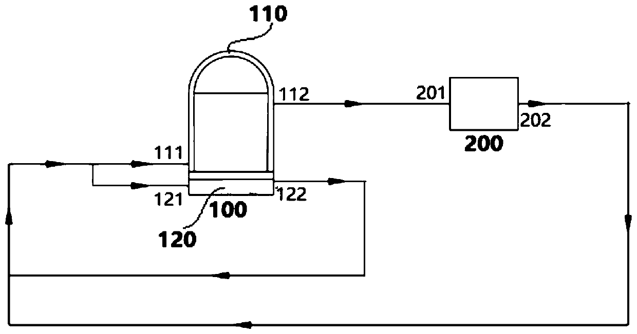
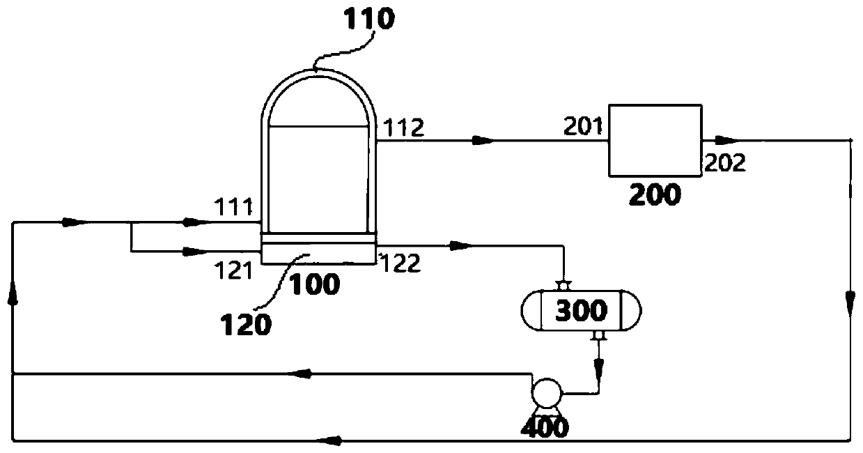
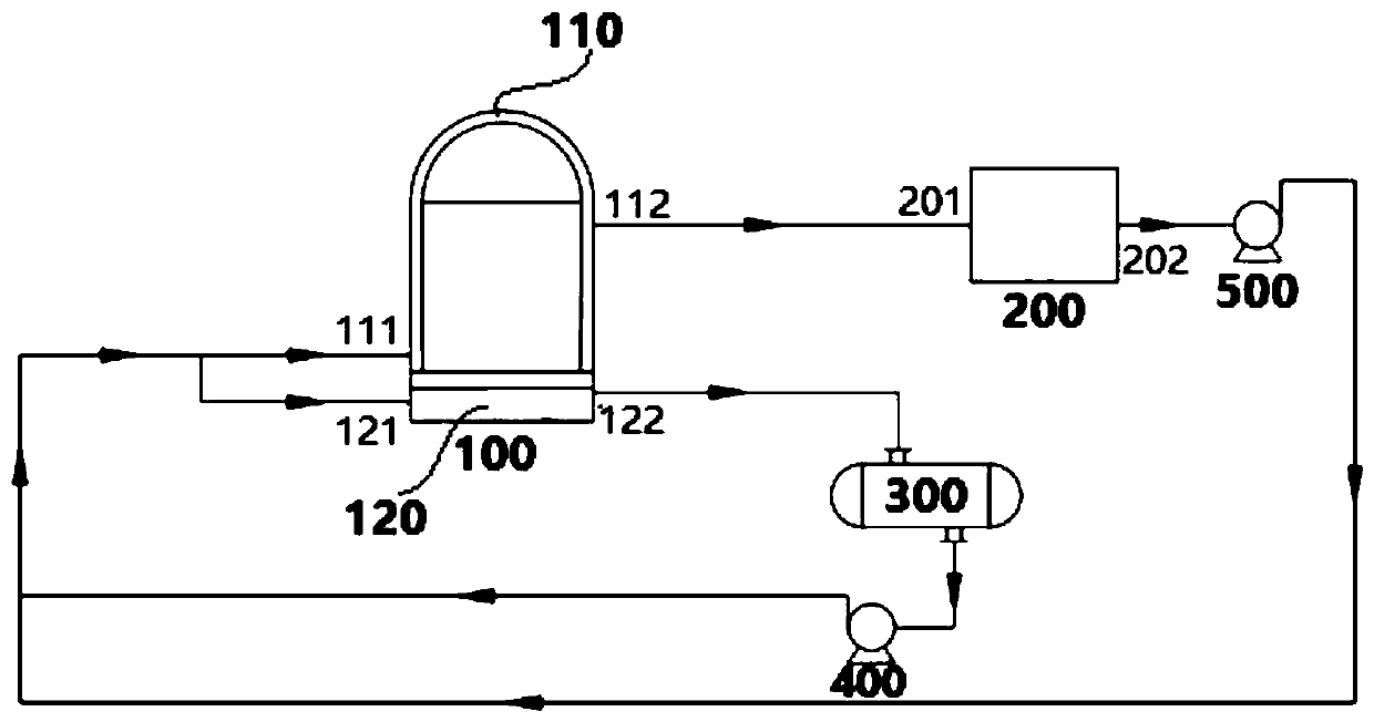
In the traditional polysilicon reduction furnace cooling system, the reduction furnace bell jar is cooled with 120-150°C high-temperature water or heat transfer oil, and the reduction furnace chassis is cooled with 60-90°C medium-temperature water. The system is complex, which makes the piping in the reduction workshop complicated, difficult to operate, and incomplete heat recovery and utilization

Method used


Image

  • Cooling system and method for polycrystalline silicon reduction furnace
  • Cooling system and method for polycrystalline silicon reduction furnace
  • Cooling system and method for polycrystalline silicon reduction furnace

Examples


Embodiment Construction

[0032]Embodiments of the present invention are described in detail below, examples of which are shown in the drawings, wherein the same or similar reference numerals designate the same or similar elements or elements having the same or similar functions throughout. The embodiments described below by referring to the figures are exemplary and are intended to explain the present invention and should not be construed as limiting the present invention.

[0033] In describing the present invention, it should be understood that the terms "center", "longitudinal", "transverse", "length", "width", "thickness", "upper", "lower", "front", " Back", "Left", "Right", "Vertical", "Horizontal", "Top", "Bottom", "Inner", "Outer", "Clockwise", "Counterclockwise", "Axial" , "radial", "circumferential" and other indicated orientations or positional relationships are based on the orientations or positional relationships shown in the drawings, which are only for the convenience of describing the p...


PUM


Abstract

The invention discloses a cooling system and method for a polycrystalline silicon reduction furnace. The system comprises a reduction furnace body and a heat exchanging device, wherein the reduction furnace body comprises a bell jar and a chassis; the bell jar is provided with a first inlet for cooling water and an outlet for bell jar high-temperature water; the chassis is provided with a second inlet for the cooling water and an outlet for chassis high-temperature water; the outlet for the chassis high-temperature water is connected with the first inlet for the cooling water and/or the second inlet for the cooling water; the heat exchanging device is provided with an inlet for the bell jar high-temperature water and an outlet for cooling water after heat exchange; the inlet for the bell jar high-temperature water and the outlet for the bell jar high-temperature water are connected; the outlet for the cooling water after heat exchange is connected with the first inlet for the cooling water and/or the second inlet for the cooling water. Through adopting the system, not only is the pipeline of an existing cooling system for the polycrystalline silicon reduction furnace is remarkably simplified, butthe efficient and graded recycling of the energy of the bell jar high-temperature water and the chassis high-temperature water is also realized; meanwhile, the remote recycling amount of the polycrystalline silicon reduction furnace cooling water is remarkably reduced, and the safe and stable operation of the polycrystalline silicon reduction furnace is realized.

Description

technical field [0001] The invention belongs to the field of polysilicon production, in particular, the invention relates to a cooling system and method for a polysilicon reduction furnace. Background technique [0002] Polysilicon is a raw material for solar photovoltaic and electronic communication products, and plays a pivotal role in the production of photovoltaic cells and electronic communication. Therefore, various systems in the production process of polysilicon are constantly being optimized and improved. Reducing the cost of polysilicon production by means of energy saving and consumption reduction is the goal pursued by polysilicon production workers all the time. Among the existing polysilicon production systems, the reduction system is the system with the highest energy consumption and the most potential potential. [0003] More than 80% of the existing polysilicon production adopts the improved Siemens process, and the polysilicon deposition reduction furnace ...

Claims


Application Information

Patent Timeline
Patent Type & Authority Applications(China)
IPC IPC(8): C01B33/035
CPCC01B33/035
Inventor 石何武张升学杨永亮郑红梅严大洲
Owner CHINA ENFI ENGINEERING CORPORATION
Why Eureka
Try Eureka