
Efficient, low-NOx and compact type self preheating type burner nozzle

A compact and high-efficiency technology, applied in the direction of burner, combustion method, combustion type, etc., can solve the problems of low heat exchange efficiency, difficulty in meeting environmental protection standards, single combustion method, etc., and achieve the effect of reducing NOx

Inactive Publication Date: 2019-09-27
FOSHAN KEHAO COMBUSTION EQUIP MFG
View PDF0 Cites 1 Cited by
  • Summary
  • Abstract
  • Description
  • Claims
  • Application Information

AI Technical Summary

Problems solved by technology

[0003] The self-preheating burner is a typical type of industrial furnace burner. The burner acts as a combustion device and a smoke exhaust device at the same time. However, the conventional self-preheating burner has a single combustion method and the heat exchange efficiency At the same time, when the traditional structure is used in the conventional combustion mode with air preheating, the amount of pollutants such as NOx is relatively large, and it is difficult to meet the environmental protection standard

Method used


Image

  • Efficient, low-NOx and compact type self preheating type burner nozzle
  • Efficient, low-NOx and compact type self preheating type burner nozzle
  • Efficient, low-NOx and compact type self preheating type burner nozzle

Examples


Embodiment 1

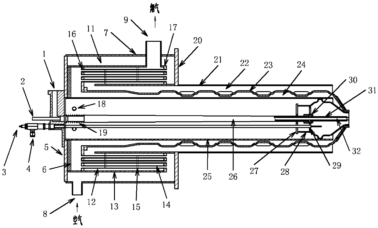
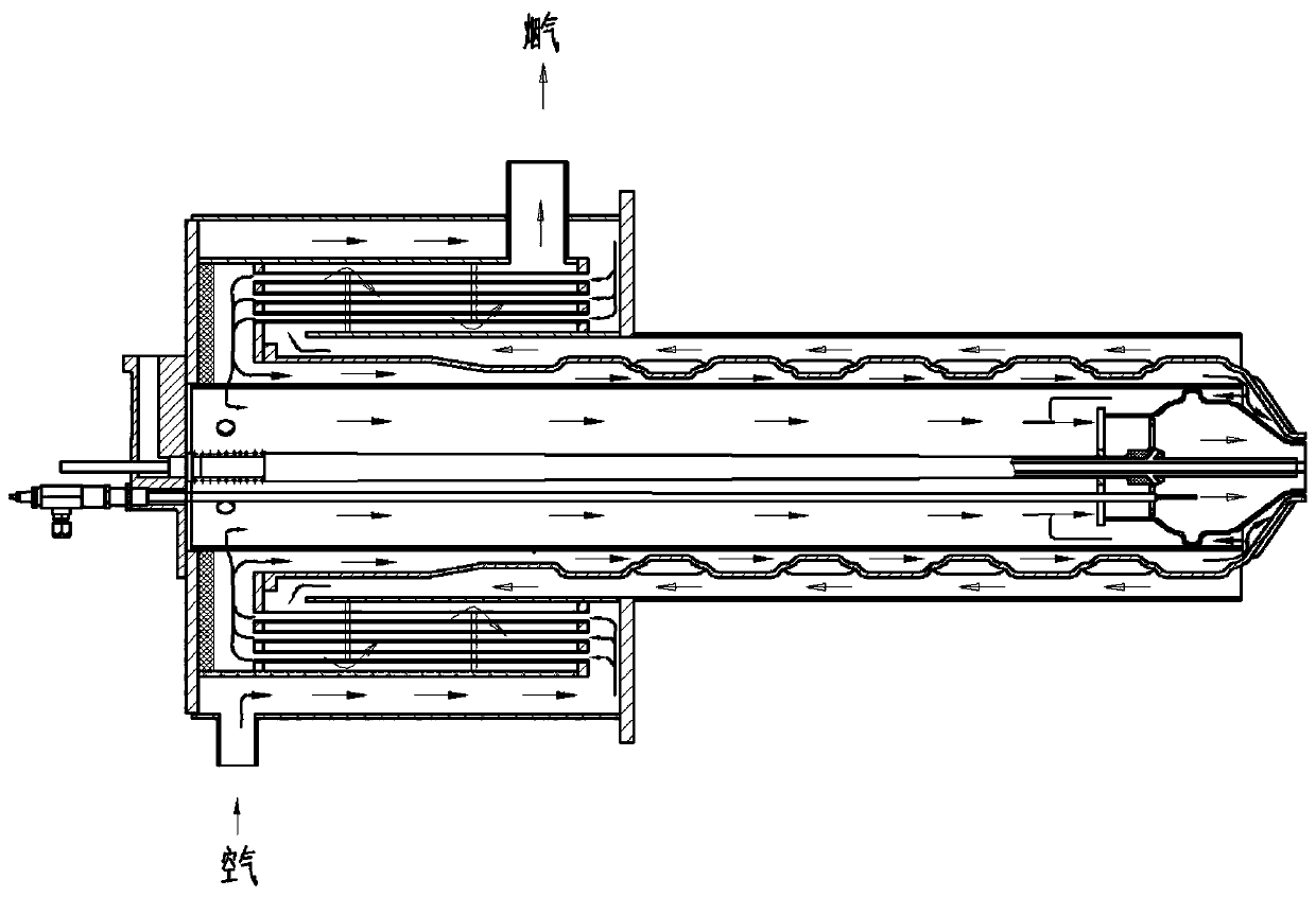
[0033] see figure 1 As shown, this embodiment is about a high-efficiency, low-NOx compact self-preheating burner, including an air pipe 25, a gas channel 26, a flue gas pipe 21, a combustion chamber 28 and an ignition electrode 3, and the combustion chamber 28 is placed in the air pipe At the opening of the front end in 25, a first ring gap is formed between the combustion chamber 28 and the air pipe 25, the ignition end of the ignition electrode 3 is arranged in the combustion chamber 28, the surface of the air pipe 25 is covered with a heat exchange tube 23, and the surface of the air pipe 25 is opened There is an air hole 18, one end of the heat exchange tube 23 extends to the combustion chamber 28 and forms a second ring gap with the outlet of the combustion chamber 28, and the rear end of the air pipe 25 is equipped with an air shell with an air inlet 8 and a smoke outlet 9 7. The flue gas pipe 21 is set on the surface of the heat exchange pipe 23, and the outer surface o...

Embodiment 2

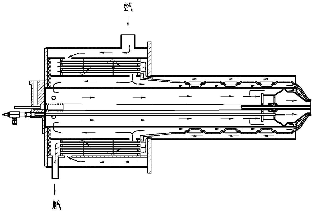
[0044] see Figure 4 As shown, the difference between this embodiment and Embodiment 1 is that the compact heat exchanger 12 does not include a shell, and the first flange 16 and the second flange 17 are ringed on the surface of the air pipe 25 and fixed to the air shell 7, the flow-around baffles 15 are fixed in the air casing 7 and distributed alternately along the extending direction of the air casing 7, one end of the heat exchange conduit 14 is fixedly arranged on the first flange 16, and the end of the heat exchange conduit 14 The other end is fixed on the second flange 17. During specific implementation, an insulating lining 6 must be added to the inner wall of the air housing 7.

[0045] Such as Figure 4 As shown, in this embodiment, the front ends of several heat exchange conduits 14 communicate with the air inlet 8 as the air heat exchange inlet, and the rear ends of the heat exchange conduits 14 communicate with the heat exchange tube 23 as the air heat exchange o...


PUM


Abstract

The invention discloses an efficient, low-NOx and compact type self preheating type burner nozzle which can recycle waste heat of exhaust gas more sufficiently, increases the temperature of preheated air to the maximum, improves the heat exchanging efficiency of the burner nozzle to be more than 80%, and greatly increases the energy-saving level of the preheating burner nozzle; in addition, the burner nozzle uses the air and fuel gas double staged combustion technology at low temperature and uses the flameless combustion technology at high temperature, so that the problem that during the entire combustion process of the burner nozzle, emission of NOx is increased due to the situation that the air is preheated and increased in temperature to cause increase of the flame temperature is solved in the most optimized manner, and the energy is saved and the environment is protected.

Description

technical field [0001] The invention relates to the field of self-preheating burners, in particular to a compact self-preheating burner with high efficiency and low NOx. Background technique [0002] Energy and the environment have always been contradictory topics in the world's industrial development. my country is one of the countries with relatively scarce resources in the world. There is a shortage of basic raw materials for industrial development. We need both green water and lush mountains, and mountains of gold and silver. This has become a new concept for the development and construction of my country's industrial ecological civilization in the future. Therefore, how to make more efficient use of the existing Energy, and compliance with national environmental protection standards has become a new trend in industrial development. [0003] The self-preheating burner is a typical type of industrial furnace burner. The burner acts as a combustion device and a smoke exhau...

Claims


Application Information

Patent Timeline
Patent Type & Authority Applications(China)
IPC IPC(8): F23D14/02F23D14/46F23D14/62F23D14/66
CPCF23D14/02F23D14/46F23D14/62F23D14/66Y02E20/34
Inventor 王建中吕永超潘映沛颜磊宋付志宋晓敏谢明勇魏长鸿
Owner FOSHAN KEHAO COMBUSTION EQUIP MFG
Learn More