Automatic machining equipment for mass production of threaded rods

An automatic processing and threaded rod technology, which is applied in other manufacturing equipment/tools, manufacturing tools, etc., can solve the problems of low processing efficiency, unfavorable mass production, burns, etc., and achieve the effects of improving processing efficiency, saving manpower, and improving hardness

Inactive Publication Date: 2019-10-01
叶玉芳
View PDF4 Cites 5 Cited by
  • Summary
  • Abstract
  • Description
  • Claims
  • Application Information

AI Technical Summary

Problems solved by technology

[0003] In order to overcome the disadvantages that it takes more manpower to process the threaded rod, it is easy to cause burns during the quenching process, the processing efficiency is low, and it is not conducive to mass production. The technical problem to be solved is: to provide a method that can save manpower and is safe Mass-produced threaded rod automatic processing equipment with high processing efficiency

Method used


Image

  • Automatic machining equipment for mass production of threaded rods
  • Automatic machining equipment for mass production of threaded rods
  • Automatic machining equipment for mass production of threaded rods

Examples


Embodiment 1

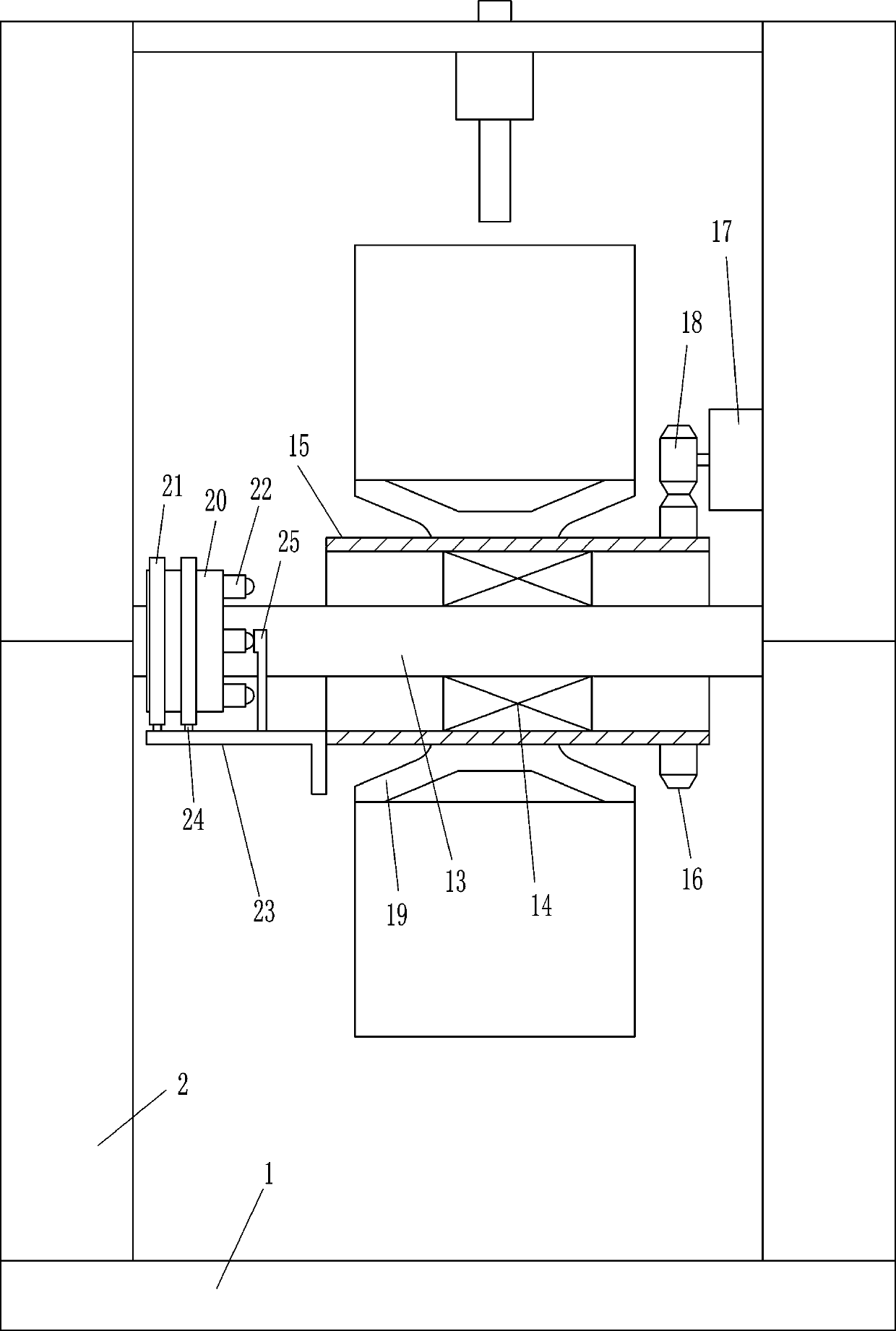
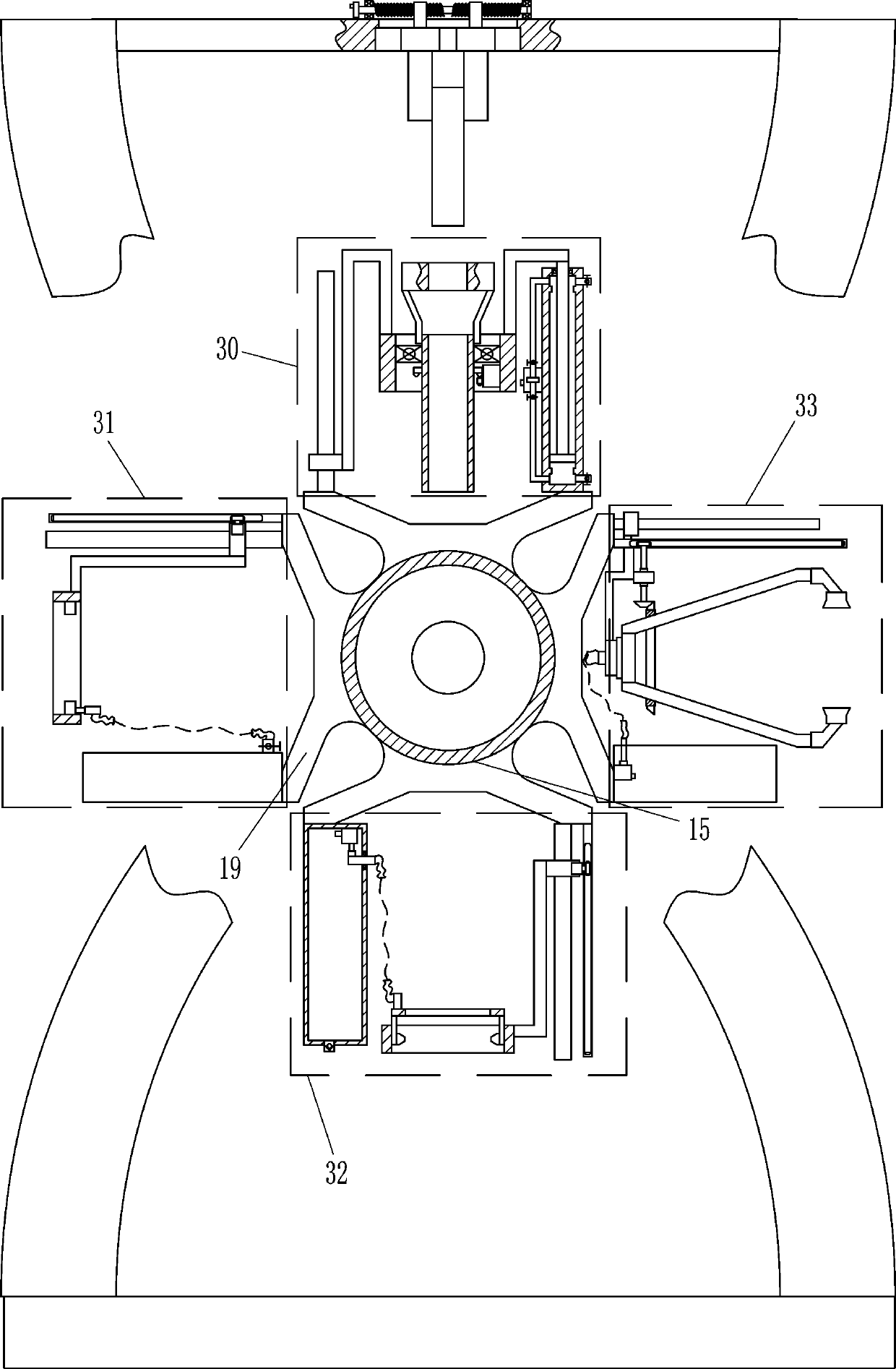
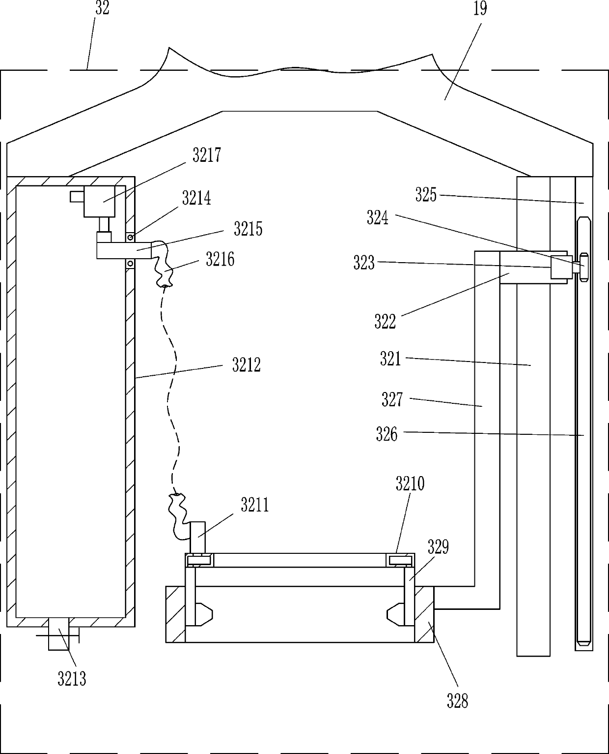
[0023] A mass-produced threaded rod automatic processing equipment, such as Figure 1-10 As shown, it includes a bottom plate 1, a control box 101, a main power switch 102, a mounting frame 2, a mounting plate 3, a slide rail 4, a slider 5, a clamp 6, a nut 8, a first bearing seat 9, and a first rotating rod 10 , Screw rod 11, handle 12, fixed rod 13, second bearing seat 14, first rotating ring 15, first gear 16, drive motor 17, second gear 18, fixed frame 19, rotating disc 20, brush 21 , contact switch 22, the first L-shaped bar 23, electrode 24, contact head 25, tapping device 30, thermal processing device 31, quenching device 32 and anti-rust treatment device 33, a control box 101 is installed in the middle of the top of the bottom plate 1, The bottom plate 1 is connected to the control box 101 by means of bolt connection. The control box 101 includes a power supply module and a control module. The main power switch 102 is connected to the top of the bottom plate 1, and th...

Embodiment 2

[0027] A mass-produced threaded rod automatic processing equipment, such as Figure 1-10As shown, it includes a bottom plate 1, a control box 101, a main power switch 102, a mounting frame 2, a mounting plate 3, a slide rail 4, a slider 5, a clamp 6, a nut 8, a first bearing seat 9, and a first rotating rod 10 , Screw rod 11, handle 12, fixed rod 13, second bearing seat 14, first rotating ring 15, first gear 16, drive motor 17, second gear 18, fixed frame 19, rotating disc 20, brush 21 , contact switch 22, the first L-shaped bar 23, electrode 24, contact head 25, tapping device 30, thermal processing device 31, quenching device 32 and anti-rust treatment device 33, a control box 101 is installed in the middle of the top of the bottom plate 1, The control box 101 includes a power supply module and a control module, the power supply module and the switching power supply are connected by a line, the control module and the power supply module are connected by a line, the front rig...

Embodiment 3

[0032] A mass-produced threaded rod automatic processing equipment, such as Figure 1-10 As shown, it includes a bottom plate 1, a control box 101, a main power switch 102, a mounting frame 2, a mounting plate 3, a slide rail 4, a slider 5, a clamp 6, a nut 8, a first bearing seat 9, and a first rotating rod 10 , Screw rod 11, handle 12, fixed rod 13, second bearing seat 14, first rotating ring 15, first gear 16, drive motor 17, second gear 18, fixed frame 19, rotating disc 20, brush 21 , contact switch 22, the first L-shaped bar 23, electrode 24, contact head 25, tapping device 30, thermal processing device 31, quenching device 32 and anti-rust treatment device 33, a control box 101 is installed in the middle of the top of the bottom plate 1, The control box 101 includes a power supply module and a control module, the power supply module and the switching power supply are connected by a line, the control module and the power supply module are connected by a line, the front ri...


PUM


Abstract

The invention relates to threaded rod machining equipment, in particular to automatic machining equipment for mass production of threaded rods. The automatic machining equipment is capable of saving manpower, high in safety and high in machining efficiency. According to the technical scheme, the automatic machining equipment comprises a bottom plate, a control box, a power main switch, an installation frame, an installation plate, a sliding rail, a sliding block, a clamp, a nut, a first bearing seat, a first rotating rod, a screw rod and the like; the control box is arranged in the middle of the top of the bottom plate and comprises a power supply module and a control module; the power supply module is connected with a switching power supply through a wire; and the control module is connected with the power supply module through a wire. According to the automatic machining equipment, a crank handle is rotated anticlockwise so as to drive the nut to move inwards through the screw rod, therefore, an iron rod is clamped through the clamp, and machining of the threaded rods is convenient; and through a tapping device, the iron rod can be tapped without using a threading die manually, so that manpower is saved.

Description

technical field [0001] The invention relates to a threaded rod processing device, in particular to an automatic processing device for a mass-produced threaded rod. Background technique [0002] Threaded rod is a commonly used mechanical part, which is often used by people. It needs to go through many steps in the process of processing. Generally, people use dies to tap on iron rods, which requires more manpower. Tapping Afterwards, another quenching treatment is required, and the quenching process is easy to cause burns. After the threaded rod is processed, anti-rust treatment is required. People use brushes to apply anti-rust oil on the surface of the threaded rod. This speed is slow, resulting in reduced processing efficiency, which is not conducive to mass production. Contents of the invention [0003] In order to overcome the disadvantages that it takes more manpower to process the threaded rod, it is easy to cause burns during the quenching process, the processing ef...

Claims


Application Information

Patent Timeline
Patent Type & Authority Applications(China)
IPC IPC(8): B23P23/04
CPCB23P23/04
Inventor 叶玉芳
Owner 叶玉芳
Why Eureka
Try Eureka