A plane receiving centrifugal spinning device

A technology of centrifugal spinning and collecting device, applied in textiles and papermaking, filament/thread forming, non-woven fabrics, etc., can solve problems such as low efficiency, low safety factor, and inability to achieve continuous production

Active Publication Date: 2021-06-15
WUHAN TEXTILE UNIV +1
View PDF11 Cites 0 Cited by
  • Summary
  • Abstract
  • Description
  • Claims
  • Application Information

AI Technical Summary

Problems solved by technology

During centrifugal spinning, the spinning head is driven by a motor to rotate, and the spinning solution is ejected from the spinneret hole of the spinning head, and moves between the spinneret hole and the collecting rod to be stretched, and at the same time, the solvent volatilizes to form fibers, which pass through The fiber film is received by the collecting rods; in this collection method, the spinning is fixed between the collecting rods, and the fibers obtained are discontinuous short fibers, which are inefficient and cannot achieve continuous production
[0005] The patent with the application number CN201820388681.7 provides a centrifugal electrospinning device, including a centrifugal spinning nozzle, a receiving device arranged above the multifilament nozzle, a driving mechanism for driving the centrifugal spinning nozzle, and a A power supply device for forming an electrostatic field required for spinning solution between the centrifugal spinning nozzle and the receiving device, the centrifugal spinning nozzle is provided with several outlet holes radially spaced from each other, the centrifugal spinning nozzle and the receiving device The spinning solution delivery device is connected; in this device, the receiving device is set above the centrifugal spinning nozzle and grounded, and the spinning jet from the centrifugal spinning nozzle is stretched under the action of centrifugal force and electric field force. This electrostatic method not only cannot realize continuous Generated, and there are problems of excessive energy consumption, low operability, and low safety factor

Method used


Image

  • A plane receiving centrifugal spinning device
  • A plane receiving centrifugal spinning device
  • A plane receiving centrifugal spinning device

Examples


Embodiment 1

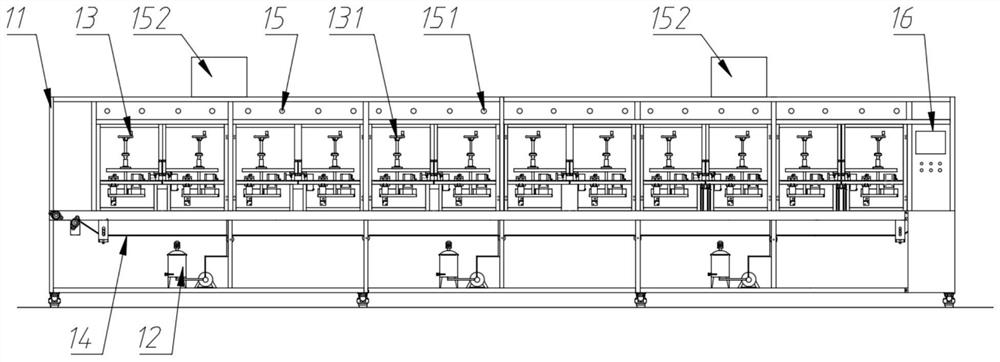
[0055] Such as figure 2 As shown, a plane receiving type centrifugal spinning device comprises a frame 11, a feeding device 12, a spinning device 13, a collection device 14, a temperature control device 15 and a control system 16; the feeding device 12 is fixedly installed on the machine The bottom of the frame 11; the temperature control device 15 is fixedly mounted on the top of the frame 11; the collecting device 14 is fixedly mounted on the middle part of the frame 11; the spinning device 13 is arranged above the collecting device 14, And it is fixedly installed on the frame 11; the control system 16 is fixedly installed on one side of the frame 11.

[0056] The feeding device 12 supplies materials to the spinning device 13; the spinning device 13 performs centrifugal spinning; the collecting device 14 collects the centrifugal spinning fiber web made by the spinning device 13; the temperature control The device 15 adjusts the temperature of the spinning environment in th...

Embodiment 2

[0086] The difference with Embodiment 1 is that, in the spinner device 133 among the embodiment 2, at least one spinneret 1354 is installed on its said spinneret 134; The shape of the spinneret shown is as follows Figure 8 As shown, its inner diameter gradually becomes smaller to form a cone; the spinning solution in the spinneret 134 is ejected through the spinneret 1354 .

Embodiment 3

[0088] The difference with embodiment 1 is that, in the spinner device 133 in embodiment 3, at least one spinneret 1354 is installed on its described spinneret 134; The shape of shown spinneret is as follows Figure 9 As shown, its structure is in the form of steps; the spinning solution in the spinneret 134 is ejected through the spinneret 1354 .


PUM


Abstract

The invention discloses a plane-receiving centrifugal spinning device. In the invention, a continuously moving collection belt is arranged under the spinneret. After adjusting a suitable height, the spinning solution sprayed out by the spinneret when rotating at a high speed instantly forms fibers. And it descends in a spiral line and collects on the collection belt, finally forming a continuous centrifugal spinning fiber web; the invention solves the problem of preparation of continuous centrifugal spinning filaments, realizes the batch production of centrifugal spinning, and is applicable to wide-width nonwovens Production of composite or wide nanometer or submicron scale nonwovens with surface nanofibers or submicron fibers.

Description

technical field [0001] The invention relates to the technical field of textiles, in particular to a plane-receiving centrifugal spinning device. Background technique [0002] Centrifugal spinning is a new spinning technology that can be applied to both solution spinning and melt spinning. Centrifugal spinning In the spinning process, the spinning solution inside the spinneret is ejected from the micropores by the centrifugal force generated by the high-speed rotating spinneret to form long and thin fibers. The materials that can be prepared include inorganic materials and polymers. Materials, combined with the characteristics of high output of centrifugal spinning and the advantages of fiber products, the fiber products prepared by it can be used in biomedicine, air filtration, energy and other fields. [0003] At present, for centrifugal spinning, the forming mechanism of its fibers has been deeply studied, and the technical problem to be solved is how to realize the conti...

Claims


Application Information

Patent Timeline
Patent Type & Authority Patents(China)
IPC IPC(8): D01D5/18D04H1/724
CPCD01D5/18D04H1/724
Inventor 刘欣吴龙涛徐卫林李晨林勇张科王亚飞陈太照王平顾绍金
Owner WUHAN TEXTILE UNIV
Why Eureka
Try Eureka