A kind of planar receiving type centrifugal spinning automatic production equipment and method

An automatic production and centrifugal spinning technology, applied in textiles and papermaking, filament/thread forming, non-woven fabrics, etc., can solve the problems of low safety factor, inability to achieve continuous production, low operability, etc., and achieve automatic deviation correction. Effect

Active Publication Date: 2021-08-10
WUHAN TEXTILE UNIV +1
View PDF8 Cites 0 Cited by
  • Summary
  • Abstract
  • Description
  • Claims
  • Application Information

AI Technical Summary

Problems solved by technology

During centrifugal spinning, the spinning head is driven by a motor to rotate, and the spinning solution is ejected from the spinneret hole of the spinning head, and moves between the spinneret hole and the collecting rod to be stretched, and at the same time, the solvent volatilizes to form fibers, which pass through The fiber film is received by the collecting rods; in this collection method, the spinning is fixed between the collecting rods, and the fibers obtained are discontinuous short fibers, which are inefficient and cannot achieve continuous production
[0005] The patent with the application number CN201820388681.7 provides a centrifugal electrospinning device, including a centrifugal spinning nozzle, a receiving device arranged above the multifilament nozzle, a driving mechanism for driving the centrifugal spinning nozzle, and a A power supply device for forming an electrostatic field required for spinning solution between the centrifugal spinning nozzle and the receiving device, the centrifugal spinning nozzle is provided with several outlet holes radially spaced from each other, the centrifugal spinning nozzle and the receiving device The spinning solution delivery device is connected; in this device, the receiving device is set above the centrifugal spinning nozzle and grounded, and the spinning jet from the centrifugal spinning nozzle is stretched under the action of centrifugal force and electric field force. This electrostatic method not only cannot realize continuous Generated, and there are problems of excessive energy consumption, low operability, and low safety factor

Method used


Image

  • A kind of planar receiving type centrifugal spinning automatic production equipment and method
  • A kind of planar receiving type centrifugal spinning automatic production equipment and method
  • A kind of planar receiving type centrifugal spinning automatic production equipment and method

Examples


Embodiment 1

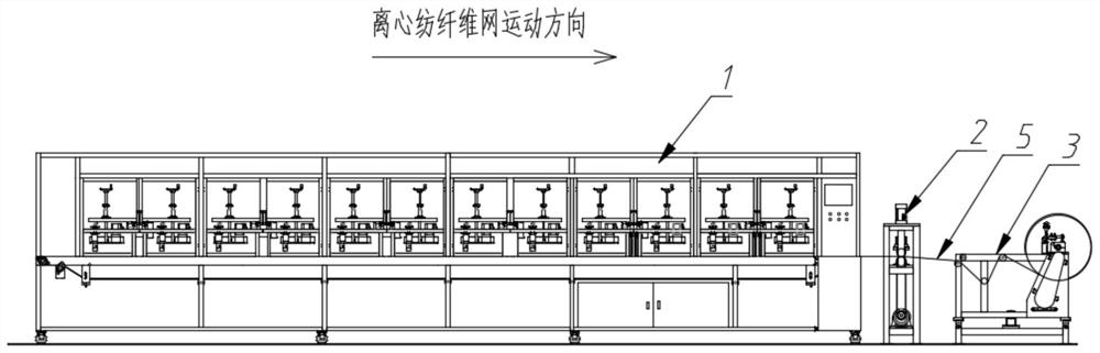
[0098] Such as figure 1 Shown, a kind of planar receiving type centrifugal spinning automatic production equipment comprises centrifugal spinning device 1, compacting device 2 and winding device 3; Described centrifugal spinning device 1, compacting device 2 and winding device 3 are according to centrifugal spinning fiber The direction of movement of the web 5 is arranged sequentially from front to back; the centrifugal spinning device 1 spins a centrifugal spinning fiber web 5; the centrifugal spinning fiber web 5 is introduced into the winding device 3 after being compacted by the compacting device 2 ; The winding device 3 winds the centrifugally spun web 5 into rolls.

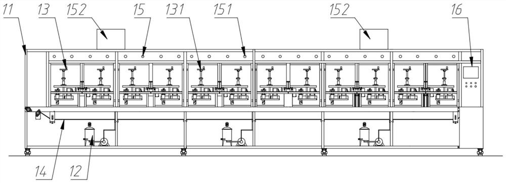
[0099] Such as figure 2 As shown, the centrifugal spinning device 1 includes a frame 11, a feeding device 12, a spinning device 13, a collecting device 14, a temperature control device 15 and a control system 16; the feeding device 12 is fixedly installed at the bottom of the frame 11 The temperature cont...

Embodiment 2

[0143] The difference with embodiment 1 is that a kind of planar receiving type centrifugal spinning equipment in embodiment 2, such as Figure 12 As shown, it also includes an unwinding device 4, which is arranged at the front end of the centrifugal spinning device 1; the unwinding device 4 is wound with a base cloth 6; the base cloth 6 penetrates into the centrifugal spinning device 1; Spinning device 1, and flat on the collection belt 142; the end of the base fabric 6 is wound on the winding roller 319 on the winding device 3.

[0144] Such as Figure 13 As shown, the unwinding device 4 includes an unwinding roller 401, an unwinding frame 402, a clamping mechanism 317, a first guide roller 303, a third guide roller 403, a second guide roller 301 and a deviation correction device 322; The moving direction of the base cloth 6, the second guide roller 301, the third guide roller 403 and the first guide roller 303 are arranged in sequence, and are fixedly installed on the unwi...

Embodiment 3

[0148] The difference with embodiment 1 is that, in the spinner device 133 in embodiment 3, at least one spinneret 1354 is installed on its said spinneret 1340; The shape of shown spinneret is as follows Figure 14 As shown, its inner diameter gradually becomes smaller to form a cone; the spinning solution in the spinneret 1340 is ejected through the spinneret 1354 .


PUM


Abstract

The invention discloses a flat receiving type centrifugal spinning automatic production equipment and method. In the invention, a continuously moving collection belt is arranged under the spinneret, and after adjusting a suitable height, the spinning solution sprayed out by the spinneret when rotating at a high speed Instantly form fibers, and descend in a spiral line to collect on the collection belt to form a continuous centrifugal spinning fiber web. The centrifugal spinning fiber web is compacted by the compacting device and then entangled in the winding device to finally form a centrifugal spinning fiber web roll; the whole The production process is automatically completed without manual intervention; the invention solves the problem of preparation of centrifugal spinning continuous filaments, realizes the batch production of centrifugal spinning, and is applicable to the composite or wide The production of nonwoven fabrics with nanometer or submicrometer scale.

Description

technical field [0001] The invention relates to the technical field of textiles, in particular to a flat receiving type centrifugal spinning automatic production equipment and method. Background technique [0002] Centrifugal spinning is a new spinning technology that can be applied to both solution spinning and melt spinning. Centrifugal spinning In the spinning process, the spinning solution inside the spinneret is ejected from the micropores by the centrifugal force generated by the high-speed rotating spinneret to form long and thin fibers. The materials that can be prepared include inorganic materials and polymers. Materials, combined with the characteristics of high output of centrifugal spinning and the advantages of fiber products, the fiber products prepared by it can be used in biomedicine, air filtration, energy and other fields. [0003] At present, for centrifugal spinning, the forming mechanism of its fibers has been deeply studied, and the technical problem t...

Claims


Application Information

Patent Timeline
Patent Type & Authority Patents(China)
IPC IPC(8): D01D5/18D04H1/724
CPCD01D5/18D04H1/724
Inventor 刘欣吴龙涛徐卫林李晨林勇张科王亚飞陈太照王平顾绍金
Owner WUHAN TEXTILE UNIV
Why Eureka
Try Eureka