Rock tensile strength in-situ test device and method
A technology for tensile strength and in-situ testing, which is applied in the direction of measuring devices, strength characteristics, and the use of stable tension/pressure to test material strength, etc., can solve the problem of high cost of rock sample processing, inaccurate measurement results, and Problems such as uneven force, to achieve accurate results, prevent slipping, and reduce friction
- Summary
- Abstract
- Description
- Claims
- Application Information
AI Technical Summary
Problems solved by technology
Method used
Image
Examples
Embodiment 1
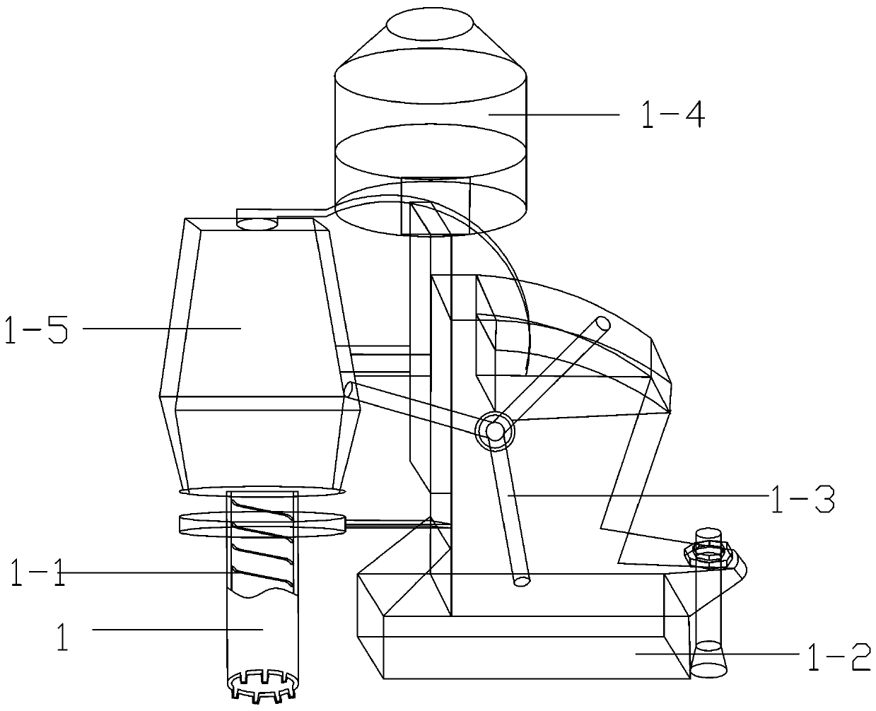
[0059] Such as Figure 1-11 Shown, a kind of rock tensile strength in-situ testing device, it comprises the coring drilling machine that is used for carrying out borehole sampling to rock sample, and described coring drilling machine comprises drilling machine base 1-2, and the core drilling machine of described drilling machine base 1-2 The top is equipped with a motor 1-4, the output shaft of the motor 1-4 is connected with the input shaft of the gearbox 1-5, and the motor 1-4 and the gearbox 1-5 are all installed on the hand-operated lifting mechanism, The hand-operated lifting mechanism cooperates with the handle 1-3 and drives it up and down; the output shaft of the gearbox 1-5 is equipped with a drill rod for drilling. By adopting the testing device with the above-mentioned structure, it can ensure that the rock pillar can be kept in the corresponding rock sample area during the testing process, thereby ensuring the accuracy of subsequent measurement data.
[0060] Furt...
Embodiment 2
[0067] The testing method of any described rock tensile strength in-situ testing device, it comprises the following steps:
[0068] When testing with half threaded drill pipe 1:
[0069] S1: Select the rock area to be measured and the measurement depth to determine the length of the semi-threaded drill pipe 1;
[0070] S2: Connect the prepared semi-threaded drill pipe 1 to the core drilling machine;
[0071] S3: Add high-temperature lubricating grease to the semi-threaded drill pipe 1 to prevent the rod from breaking due to excessive torque during coring;
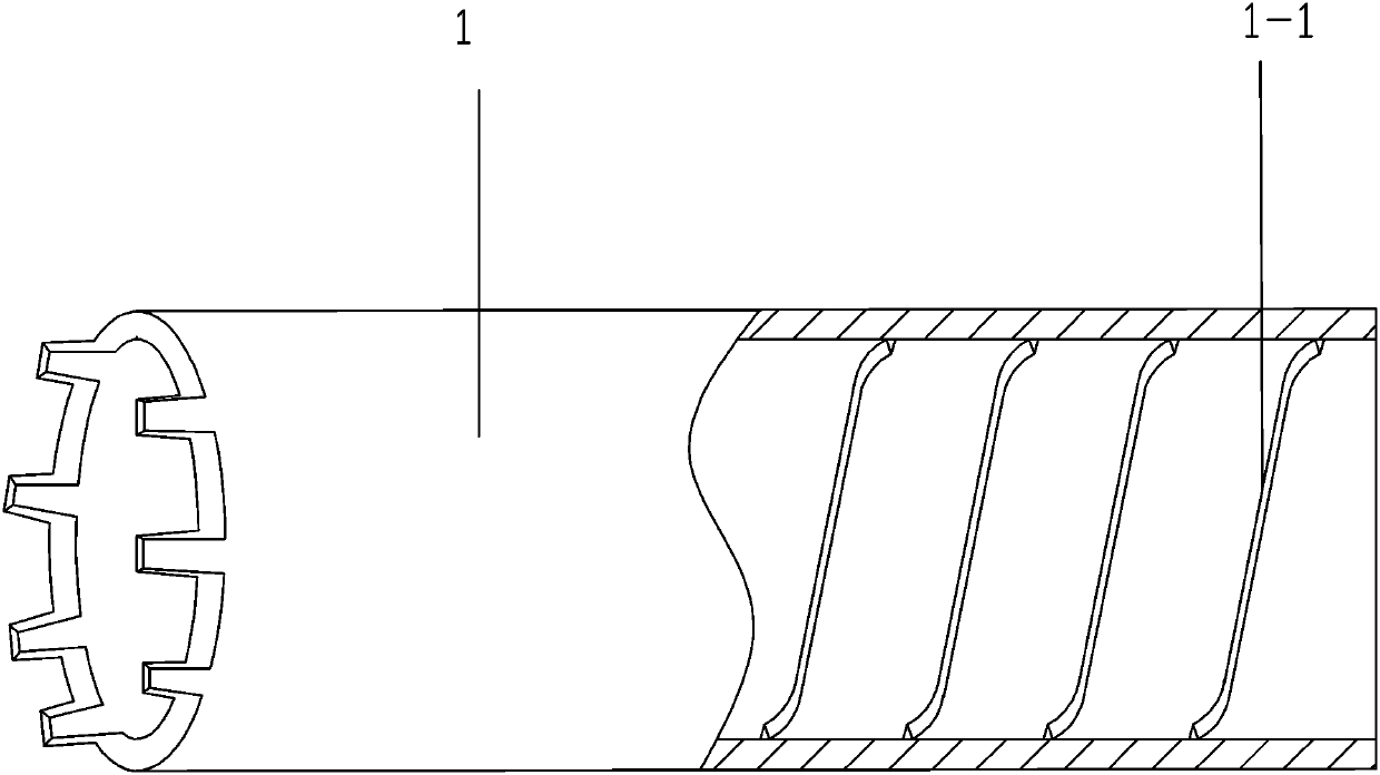
[0072] S4: Start the core drilling machine, drill into the corresponding depth in the planned area, and generate multiple turns of threads at the end of the rock sample column, and the internal thread 1-1 on the half-threaded drill pipe 1 matches the thread on the rock sample column , so that the semi-threaded drill pipe 1 tightens the rock sample column;
[0073] S5: Separate the semi-threaded drill pipe 1 from the dril...
Embodiment 3
[0076] When testing with shrink-clamped drill pipe 2:
[0077] S1: Select the rock area to be measured and the measurement depth to determine the length of the contraction-clamping drill pipe 2;
[0078] S2: Connect the prepared shrink clamping drill rod 2 to the core drilling machine;
[0079] S3: Add high-temperature lubricating grease to the shrink-clamping drill pipe 2 to prevent the rod from breaking due to excessive torque during coring;
[0080] S4: Start the core drilling rig, drill into the corresponding depth in the planned area, take down the drilling rig, pour industrial alcohol or gasoline into the shrink clamping drill pipe 2 to clean the grease, and wait until the gasoline or alcohol is completely volatilized;
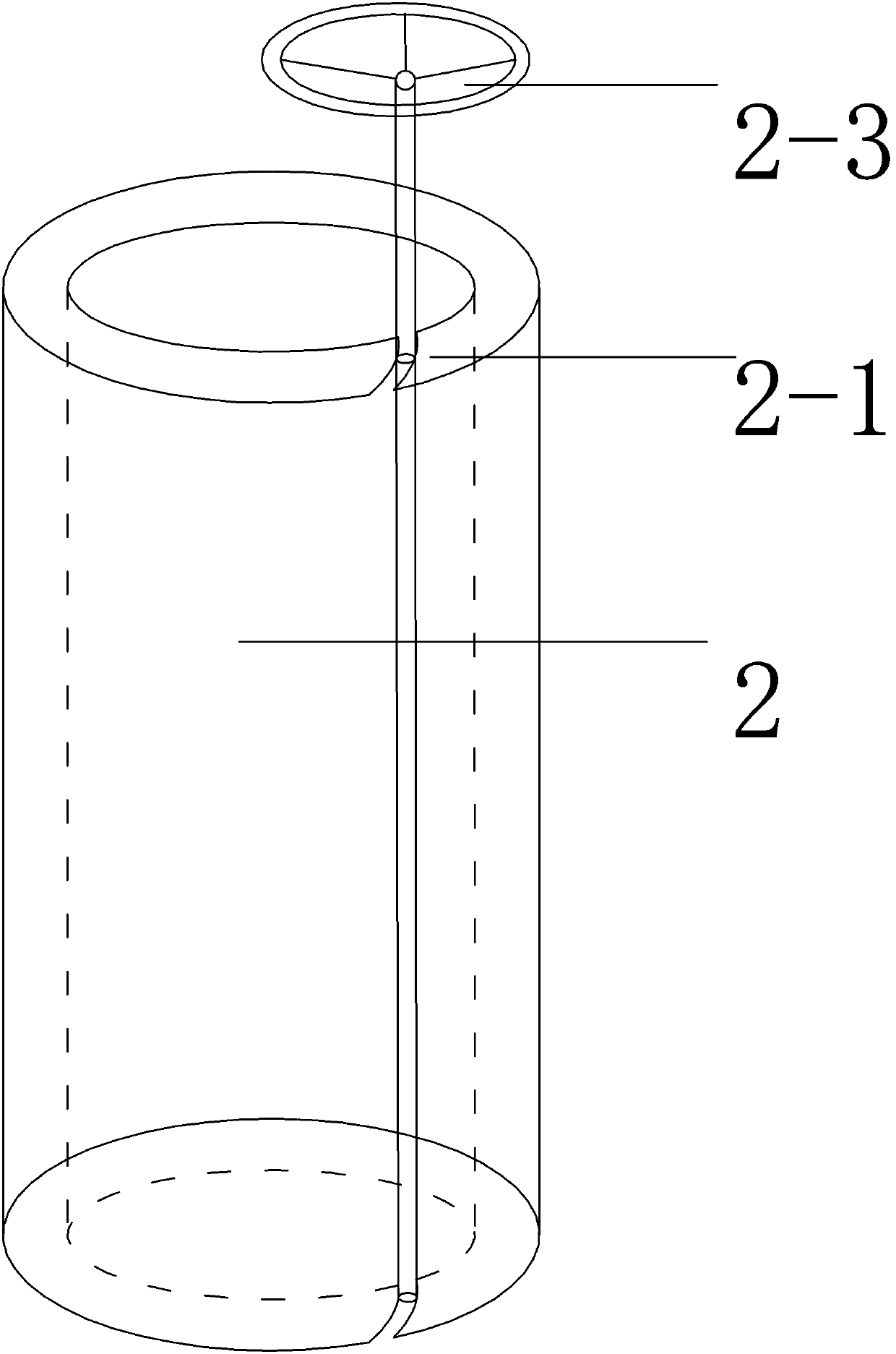
[0081] S5: Connect the turntable 2-3 to the hollow rotating shaft 2-1 of the drill pipe, turn the turntable 2-3, and tighten the retractable clamping drill pipe 2 through the gear structure to reduce the diameter of the shrinkable clamping drill pipe 2 ...
PUM
 Abstract
Description
Claims
Application Information
 - R&D
- Intellectual Property
- Life Sciences
- Materials
- Tech Scout
- Unparalleled Data Quality
- Higher Quality Content
- 60% Fewer Hallucinations
Browse by: Latest US Patents, China's latest patents, Technical Efficacy Thesaurus, Application Domain, Technology Topic, Popular Technical Reports.
© 2025 PatSnap. All rights reserved.Legal|Privacy policy|Modern Slavery Act Transparency Statement|Sitemap|About US| Contact US: help@patsnap.com


