A centrifugal spinning system for sheath-core fiber

A technology of skin-core fiber and leather material, which is applied in the centrifugal spinning system and the field of centrifugal spinning, and can solve the problems that the skin-core structure spinning fiber cannot be produced.

Active Publication Date: 2020-10-27
临沭县济才人力资源服务有限公司
View PDF1 Cites 0 Cited by
  • Summary
  • Abstract
  • Description
  • Claims
  • Application Information

AI Technical Summary

Problems solved by technology

[0006] The purpose of the present invention is to overcome the defects and problems existing in the prior art that cannot generate skin-core structure spun fibers, and provide a centrifugal spinning system for skin-core fibers capable of producing skin-core structure spun fibers

Method used


Image

  • A centrifugal spinning system for sheath-core fiber
  • A centrifugal spinning system for sheath-core fiber
  • A centrifugal spinning system for sheath-core fiber

Examples


Embodiment 1

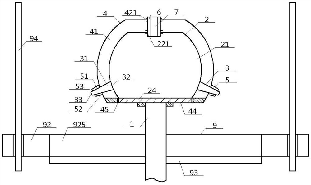
[0058] see figure 1 - Figure 11 , a centrifugal spinning system for sheath-core fibers, comprising a core rotating container 2, a core injection pipe 3 and a collecting device 9, the core rotating container 2 is surrounded by a collecting device 9, and the inside of the core rotating container 2 is provided with a core Material cavity 21, the inside of core injection pipe 3 is provided with core tube cavity 31, and core material cavity 21 communicates with core outlet 33 after passing through core inlet 32, core tube cavity 31 successively, and core inlet 32 ​​is connected with the side wall of core rotating container 2 connected, and the core outlet 33 is located inside the collection device 9; the centrifugal spinning system also includes the skin rotating container 4 and the skin injection pipe 5, and the collection device 9 includes a ventilation ring disk 92, a bottom concave disk 93 and four collecting Rod 94, the ventilation ring plate 92 includes a top ring plate sur...

Embodiment 2

[0060] Basic content is the same as embodiment 1, the difference is:

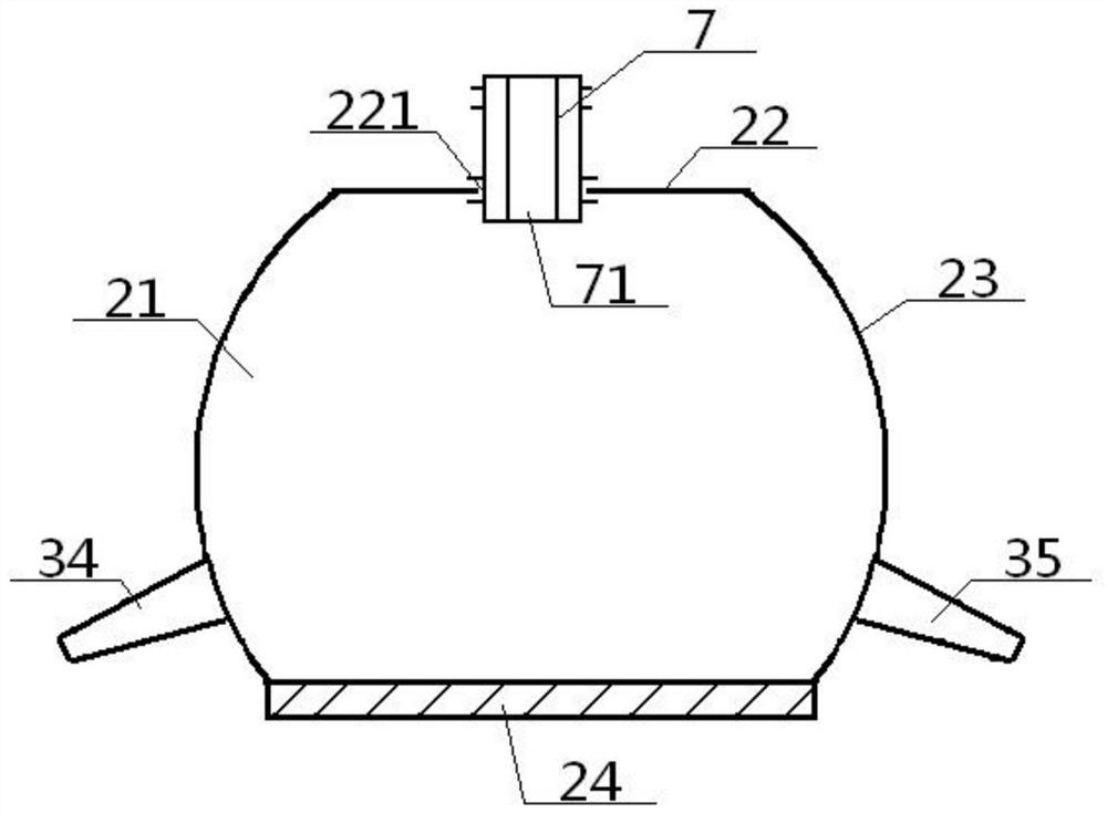
[0061] The leather rotating container 4 comprises a leather top plate 42, a leather ball circumference 43 and a leather bottom 44, the bottom surface of the leather bottom 44 is connected with the top of the rotating rod 1, and the middle part of the leather bottom 44 is provided with a leather Groove 45, the peripheries of the top surface of leather device bottom layer 44 are connected with the periphery of leather device top plate 42 through skin device ball circumference 43, and leather device top plate 42, leather device bottom plate 44 are mutually parallel up and down; Described core rotating container 2 comprises Core device top plate 22, core device spherical circumference 23 and core device bottom layer 24, described core device top plate 22 and core device bottom layer 24 are parallel to each other up and down, and the periphery of core device top plate 22 passes the top of core device spherical ci...

Embodiment 3

[0063] Basic content is the same as embodiment 1, the difference is:

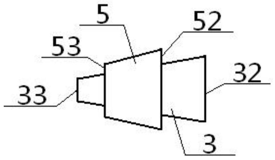
[0064]The top ring disk surface 921 is provided with four top arc surface areas 9211 uniformly arranged along the same circumference, and a top arc surface area 9212 is sandwiched between adjacent top arc surface areas 9211, and each top arc surface area 9211 Both are provided with a plurality of top air holes 9213, and the bottom ring surface 923 is provided with four bottom arcuate areas 9231 evenly arranged along the same circumference, and a bottom notch area 9232 is sandwiched between adjacent bottom arcuate areas 9231 , each bottom arc surface area 9231 is provided with a plurality of bottom air holes 9233, the bottom air holes 9233 correspond to the top air holes 9213 one by one, the bottom missing surface area 9232 corresponds to the top arc surface area 9211, and the bottom missing surface area The bottom socket 952 provided in 9232 corresponds to the top socket 951 provided in the top arc surface ...


PUM


Abstract

A sheath core fiber centrifugal spinning system comprises a ventilation ring disk, a bottom recessed disk, a core rotating container, a core injection pipe, a sheath rotating container, a sheath injection pipe and a collecting rod. The core rotating container is positioned in the sheath rotating container, the sheath rotating container and the bottom recessed disk are positioned on the upper portion and the lower portion of an inner disk cavity in the ventilation ring disk, the core injection pipe and the sheath injection pipe are connected with the core rotating container and the sheath rotating container, the sheath injection pipe externally sleeves the core injection pipe, and the bottom end of the rotating rod connected at the bottom of the sheath rotating container sequentially penetrates the inner disk cavity and the bottom recessed disk and extends to the lower portion of the bottom recessed disk. According to the design, a spinning fiber with a sheath core structure can be generated, materials can be supplied on line, product quality is high, guidance and adjustability are high, and collecting effects are good.

Description

technical field [0001] The invention relates to a centrifugal spinning technology, which belongs to the field of textile technology, and in particular to a centrifugal spinning system for sheath-core fibers, which is particularly suitable for obtaining and collecting spun fibers with a sheath-core structure by means of centrifugal spinning . Background technique [0002] Nanofibers refer to ultrafine fibers with a diameter of tens to hundreds of nanometers, which are widely used in textile materials, tissue engineering scaffolds, drug delivery, filter media, artificial blood vessels, biochips, nanosensors, optics, composite materials and other fields. Methods for preparing nanofibers include stretching, microphase separation, template synthesis, self-assembly, electrospinning, centrifugal spinning, etc., wherein centrifugal spinning refers to the process of polymer melt or solution produced by a high-speed rotating device. Centrifugal force and shear force are thrown out of...

Claims


Application Information

Patent Timeline
Patent Type & Authority Patents(China)
IPC IPC(8): D01D5/18D01D5/34
CPCD01D5/18D01D5/34
Inventor 张智明张彪徐巧姬巧玲梅顺齐肖人彬
Owner 临沭县济才人力资源服务有限公司
Why Eureka
Try Eureka