Built-in self-test method and system of FPGA input and output logic module

A logic module, input and output technology, applied in the electronic field, can solve the problems of high requirements, high test cost, inconvenient test, etc.

Inactive Publication Date: 2019-10-08
SHENZHEN PANGO MICROSYST CO LTD
View PDF10 Cites 13 Cited by
  • Summary
  • Abstract
  • Description
  • Claims
  • Application Information

AI Technical Summary

Problems solved by technology

[0004] The built-in self-test method and system of the FPGA input-output logic module provided by the embodiments of the present invention mainly have the technic

Method used


Image

  • Built-in self-test method and system of FPGA input and output logic module
  • Built-in self-test method and system of FPGA input and output logic module
  • Built-in self-test method and system of FPGA input and output logic module

Examples


Embodiment 1

[0042] At present, the application of domestic FPGA mainly depends on the import of several international FPGA giants such as Xilinx and Altera. Domestic FPGA design has technical barriers such as difficult design, long R&D cycle, and difficult design. Especially in terms of the testing methods of each module in the FPGA testing stage, the domestic FPGA field can be said to be a blank, the main reason is that foreign giant companies have mastered the advanced technology in this area but do not disclose it to the public. There is less research, so that the technology accumulation in this area is too little, the design technology is more difficult, and important technologies cannot be broken. In order to solve the problems in the related art that the IOL test scheme relies heavily on external test equipment, the test cost is high, and the test is inconvenient, this embodiment provides a new IOL test scheme. In this IOL test scheme, a kind of FPGA IOL built-in self-test system is...

Embodiment 2

[0064] This embodiment will combine the built-in self-test system of the aforementioned FPGA input-output logic module and the IOL test structure to propose a built-in self-test method for the FPGA input-output logic module. Figure 1-6 combined on the basis of Figure 7 , Figure 7 Shown is the flowchart of the built-in self-test method of the FPGA input and output logic module:

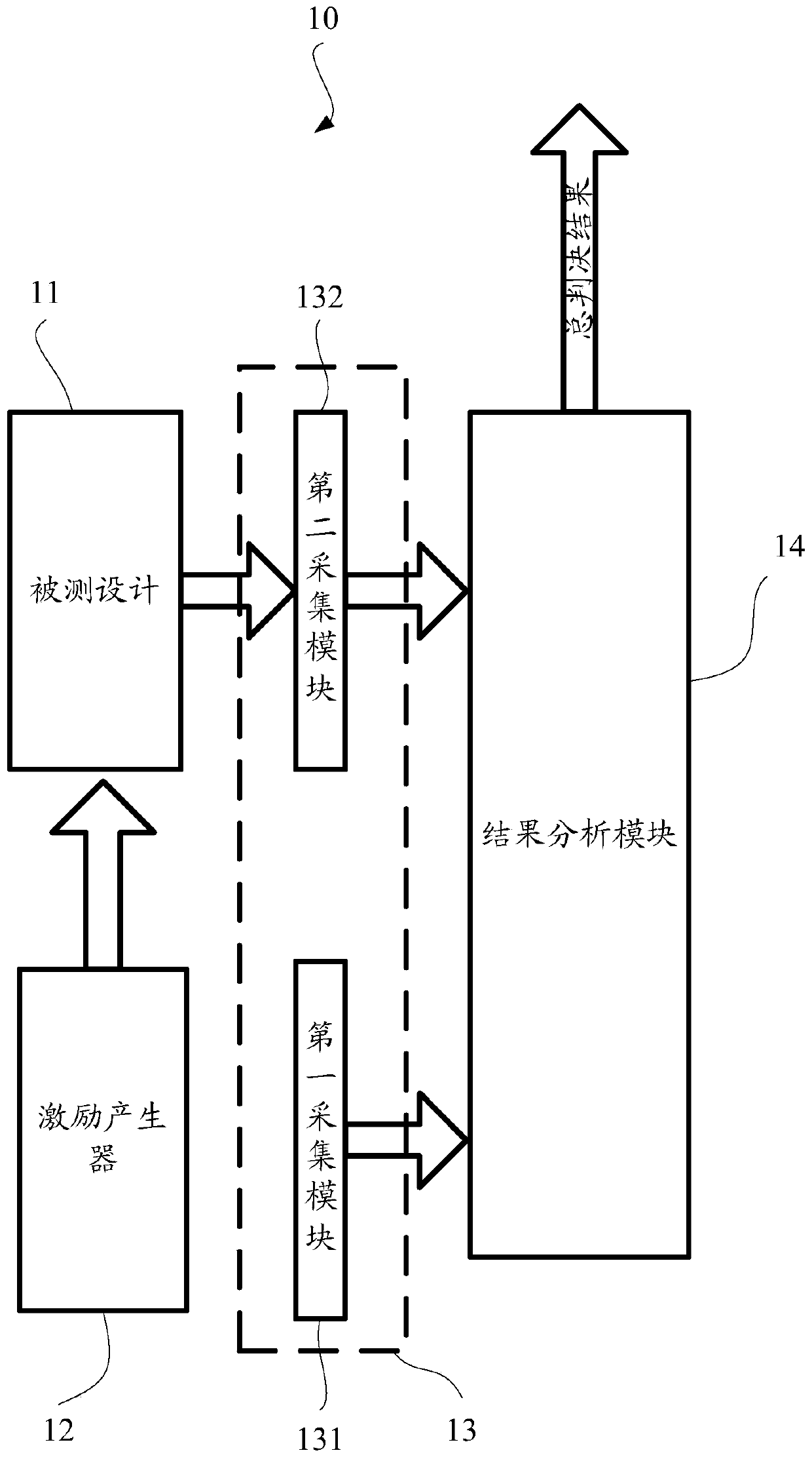
[0065] S702: Configuring an IOL testing framework for testing the IOL in the FPGA.

[0066] The specific structure of the IOL test framework 10 has been introduced in detail above, and will not be repeated here.

[0067] It can be understood that the test scheme adopted in this embodiment is a BIST (Built-in Self Test, built-in self-test) scheme, so the IOL test framework 10 is directly implemented inside the FPGA without the participation of external test equipment : There is no doubt that the IOL of the tested design is inside the FPGA, and the excitation generator 12, the output acquisition mo...

Embodiment 3

[0085] The built-in self-test system and method of the IOL test framework, FPGA input and output logic modules provided in the aforementioned embodiments, although it can be judged whether each IOL in an FPGA is faulty, because the result analysis module is only a whole for the external test equipment The final judgment result can only indicate whether there is an IOL fault in the FPGA as a whole. Therefore, if there are IOL failures in the FPGA, the tester will not be able to determine how many and which IOL failures are in the FPGA. As a result, testers need to spend a lot of time and energy on fault location.

[0086] In order to further solve the above problems, the present embodiment also provides a new IOL test framework and a built-in self-test system of FPGA input and output logic modules, please refer to Figure 8 The IOL test architecture 80 is shown:

[0087] The IOL test structure 80 includes a design under test 81 , a stimulus generator 82 , an output acquisitio...


PUM


Abstract

The invention provides a built-in self-test method and system of an FPGA input and output logic module. A PAD of an FPGA is configured, so that ISERDES and OSERDES belonging to the same IOL are communicated with the external of the FPGA, a serial data path is formed, the IOL can transfer data in a round trip way from a TX port to an RX port, and further the ISERDES and OSERDES are tested simultaneously by using a test vector generated by an excitation generator. At least one of first and second collection modules can be processed in a delayed way, and thus, the test scheme is highly repetitive; and a result analysis module can finally determine whether a tested design has a fault, so that requirements for external test equipment is low, and the test cost is reduced.

Description

technical field [0001] The invention relates to the field of electronic technology, in particular to a built-in self-test method and system for FPGA input and output logic modules. Background technique [0002] With the development needs of information and data technology, programmable chips, especially field-programmable gate array (Field-Programmable Gate Array, FPGA), with its advantages of flexible programming, stable system, rich resources and high integration, its application fields It has expanded from the original communication field to a wide range of fields such as aerospace, consumer electronics, industrial control, test and measurement, and there is a trend of continuous expansion. IOL (IO Logic, input and output logic) is the logical processing unit of the FPGA external interface IO module. It mainly converts the data input by PAD (pin) into parallel data through ISERDES (deserializer) for internal use in FPGA, and through OSERDES (Serializer) converts parallel...

Claims


Application Information

Patent Timeline
IPC IPC(8): G01R31/28G01R31/317
CPCG01R31/2846G01R31/317G01R31/31712G01R31/31718
Inventor 邢亚楠
Owner SHENZHEN PANGO MICROSYST CO LTD
Why Eureka
Try Eureka