
Pixel-level time and intensity digital conversion circuit

A digital conversion, pixel-level technology, applied in the field of circuits, can solve problems such as limited pixel unit area, inability to integrate peak hold circuits, etc., to achieve the effect of increasing operating frequency and reducing difficulty

Pending Publication Date: 2019-10-08
SUZHOU R&D CENT OF NO 214 RES INST OF CHINA NORTH IND GRP
View PDF0 Cites 0 Cited by
  • Summary
  • Abstract
  • Description
  • Claims
  • Application Information

AI Technical Summary

Problems solved by technology

At present, the commonly used method to extract the intensity information of the target echo is to select some pixel units, and perform intensity quantization through the peak hold circuit and the analog-to-digital conversion circuit outside the pixel array. The unit's internal integrated peak hold circuit

Method used


Image

  • Pixel-level time and intensity digital conversion circuit

Examples


Embodiment Construction

[0024] The present invention will be further described below in conjunction with the accompanying drawings. The following examples are only used to illustrate the technical solution of the present invention more clearly, but not to limit the protection scope of the present invention.

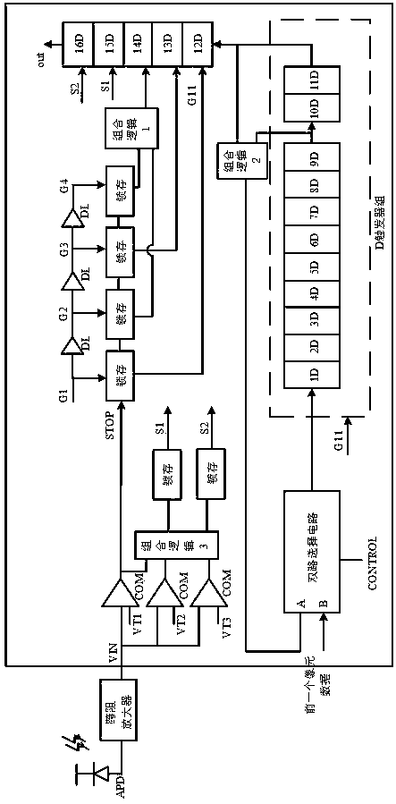
[0025] Such as figure 1 As shown, this embodiment is composed of D flip-flops 1D-16D, latch circuits, delay unit DL, dual-way selection circuits, comparator circuits, and combinational logic circuits.

[0026] G1 is the clock signal; VT1, VT2 and VT3 are the threshold voltages of the comparators; the control signal CONTROL controls the two-way selection circuit.

[0027] 1D-16D are all D flip-flops triggered by the falling edge of the clock signal G11.

[0028] D flip-flops 1D to 11D form a flip-flop group, each D flip-flop is connected in sequence, and the output end of the previous flip-flop is connected with the input end of the next flip-flop. In the timing stage, it is used as a counter ...


PUM


Abstract

The invention discloses a pixel-level time and intensity digital conversion circuit. The invention achieves a pixel-level time and intensity digital conversion circuit, for one-time laser pulse, all pixel units can give time information and intensity information of echo signals, in the data reading stage, a row and column selection control circuit is not needed, and all pixel information of each row is read sequentially, thereby greatly improving the working frequency of an area array reading circuit; the information representing the time and intensity of the echo signals is directly output ina digital format, and an on-chip ADC is not required to be quantified twice, thereby reducing the difficulty of design of the on-chip system.

Description

technical field [0001] The invention relates to a time and intensity digital conversion circuit, which belongs to the technical field of circuits. Background technique [0002] Lidar is an active detection technology that can accurately and quickly obtain three-dimensional space information on the ground or the atmosphere, and can be used for ranging and angle measurement, so it has been widely used in military and civilian fields. Imaging lidar is divided into a variety of working modes, such as scanning imaging using unit or line detectors and non-scanning imaging using array detectors. The scanning imaging distance of the unit or line array detector can be very far, but the imaging rate will be limited; while the imaging speed of the array detector is very fast, and at the same time overcome the shortcomings of the scanning type, such as large volume, heavy quality, and poor reliability. , plays a vital role in the relative navigation application of space targets with hi...

Claims


Application Information

Patent Timeline
Patent Type & Authority Applications(China)
IPC IPC(8): G01S7/486G01S7/487
CPCG01S7/4863G01S7/4865G01S7/487
Inventor 白涛刘小淮陈远金
Owner SUZHOU R&D CENT OF NO 214 RES INST OF CHINA NORTH IND GRP
Learn More