Carbon rod cutting device and coating instrument evaporation assembly with the carbon rod cutting device

A cutting device and carbon rod technology, applied in the field of mineral testing, can solve the problems of fast loss of carbon rod tip, low spraying efficiency, uneven thickness of carbon film, etc.

Active Publication Date: 2020-10-23
CHINA PETROLEUM & CHEM CORP +1
View PDF6 Cites 0 Cited by
  • Summary
  • Abstract
  • Description
  • Claims
  • Application Information

AI Technical Summary

Problems solved by technology

[0008] The technical problem to be solved by the present invention is: the tip of the carbon rod used for vapor deposition in the prior art wears quickly, and the size of the tip of the carbon rod is not easy to control, so that the thickness of the carbon film produced by spraying is not uniform, and the spraying efficiency is reduced. Low, not conducive to the development of batch sample spraying work

Method used

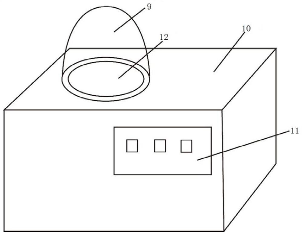
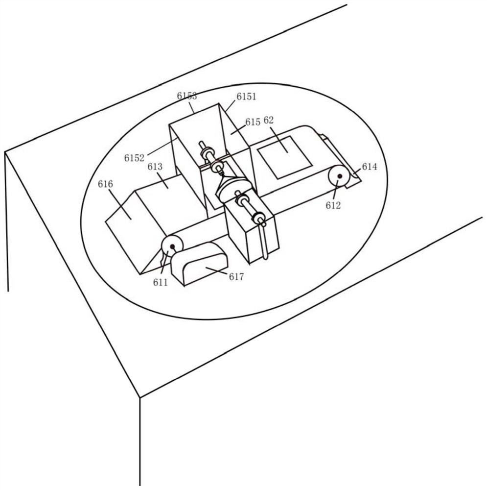
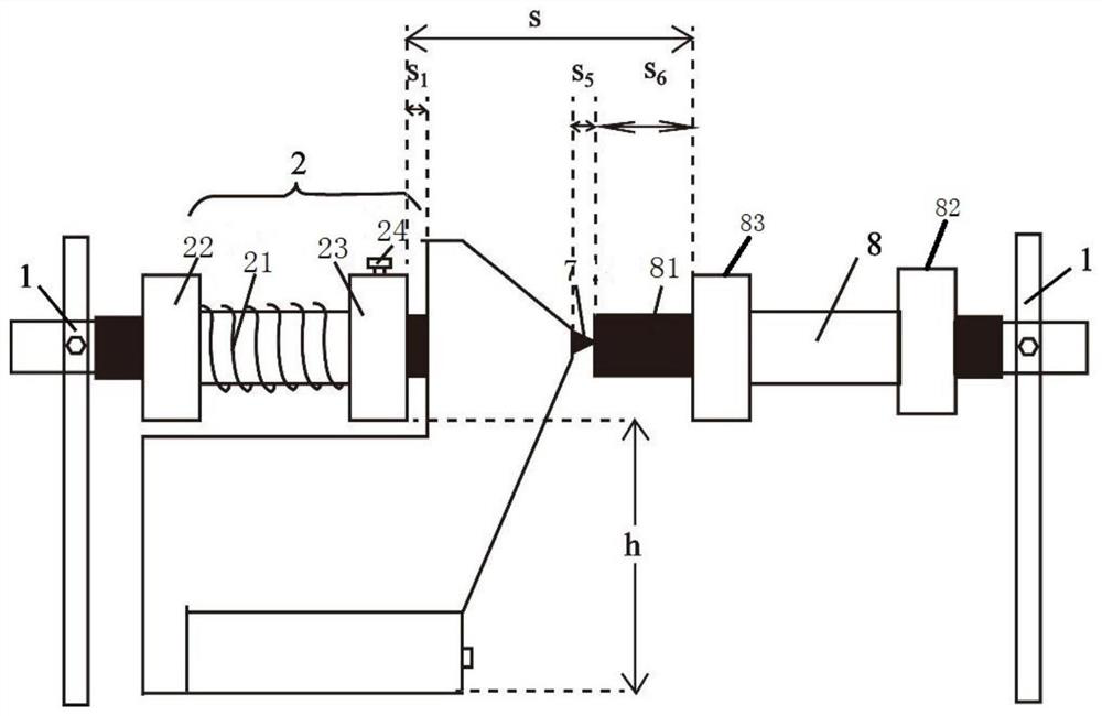

Image

  • Carbon rod cutting device and coating instrument evaporation assembly with the carbon rod cutting device
  • Carbon rod cutting device and coating instrument evaporation assembly with the carbon rod cutting device
  • Carbon rod cutting device and coating instrument evaporation assembly with the carbon rod cutting device

Examples


Embodiment Construction

[0049] The implementation of the present invention will be described in detail below in conjunction with the accompanying drawings and examples, so as to fully understand and implement the process of how to apply technical means to solve technical problems and achieve technical effects in the present invention. It should be noted that, as long as there is no conflict, each embodiment and each feature in each embodiment of the present invention can be combined with each other, and the formed technical solutions are all within the protection scope of the present invention.

[0050]In order to solve the problem that the tip of the carbon rod used for vapor deposition in the prior art is fast worn out, and the size of the tip of the carbon rod is not easy to control, so that the thickness of the sprayed carbon film is not uniform, which leads to low spraying efficiency, which is not conducive to batch samples To solve the technical problem of spraying work, the embodiment of the pr...


PUM

PropertyMeasurementUnit
thicknessaaaaaaaaaa
heightaaaaaaaaaa
lengthaaaaaaaaaa

Abstract

The invention provides a carbon rod cutting device and a film coating instrument evaporation assembly provided with the same. The carbon rod cutting device comprises a carbon rod propelling portion, acarbon rod cutting portion, a carbon rod containing portion and an electric control portion. The carbon rod propelling portion comprises an elastic component, a fixed end and a movable end, wherein the fixed end is provided with a first through hole, and the movable end is provided with a second through hole. The two ends of the elastic component are connected with the fixed end and the movable end. After penetrating the first through hole and the second through hole, the output end of each carbon rod synchronously moves together with the movable end. The carbon rod cutting portion comprisesan inlet limiting component, a tool and an outlet limiting component. The tool is arranged to be used for receiving the carbon rods moved by the carbon rod propelling portion, cutting the output endsof the carbon rods and only allowing parts of the cut carbon rods with the diameters being within the preset range to pass through. In this way, the sizes of the sharp ends of the output ends of the carbon rods for evaporation can be effectively controlled; the sizes can be uniform and meet the spraying requirement all the time; and thus, the good foundation is laid for achieving continuous multi-batch spraying operation.

Description

technical field [0001] The invention relates to the technical field of mineral testing, in particular to a carbon rod cutting device and an evaporation assembly of a coating instrument with the carbon rod cutting device. Background technique [0002] At present, most of the samples tested by electronic probes are non-conductive rock and mineral samples. Before the sample analysis and testing, it is generally necessary to coat the thin slice samples of the electronic probe to prevent the discharge phenomenon on the surface of the samples. In actual operation, due to the disadvantages of high cost and strong signal absorption of the gold film, most samples are conductively treated by evaporative carbon plating. However, due to the influence of the vacuum requirements of the spraying environment and the diffusion range of carbon vapor, the efficiency of spraying is low. Generally, a complete coating process takes about 3-4 hours. [0003] Through the analysis of the carbon spr...

Claims


Application Information

Patent Timeline
Patent Type & Authority Patents(China)
IPC IPC(8): B23D79/00C23C14/06C23C14/24
CPCB23D79/00C23C14/0605C23C14/24
Inventor 刘佳宜刘全有邱登峰孟庆强黄振凯云金表朱东亚
Owner CHINA PETROLEUM & CHEM CORP
Why Eureka
Try Eureka