Eureka AIR delivers breakthrough ideas for toughest innovation challenges, trusted by R&D personnel around the world.

Centralized cooling oil cooling unit and control method

A control method and oil cooling technology, applied in refrigerators, refrigeration components, irreversible cycle compressors, etc., can solve the problems of high cost and heavy load, and achieve the effect of reducing production cost, reducing air conditioning load and saving space.

Inactive Publication Date: 2019-10-11
GREE ELECTRIC APPLIANCES INC
View PDF4 Cites 0 Cited by
  • Summary
  • Abstract
  • Description
  • Claims
  • Application Information

AI Technical Summary

Problems solved by technology

[0004] In order to solve the defects of large load and high cost in the prior art, the present invention proposes an oil cooling unit for centralized cooling and a control method

Method used

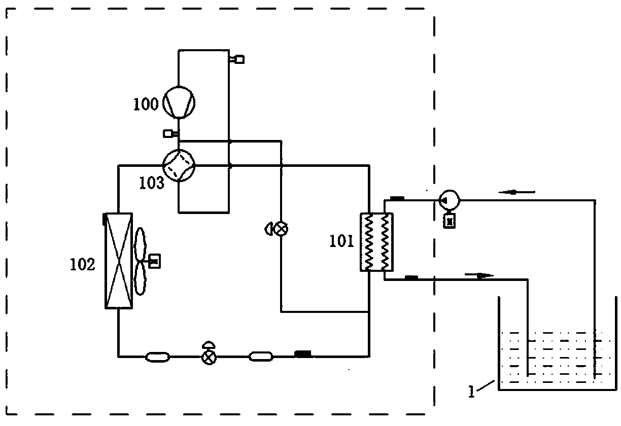
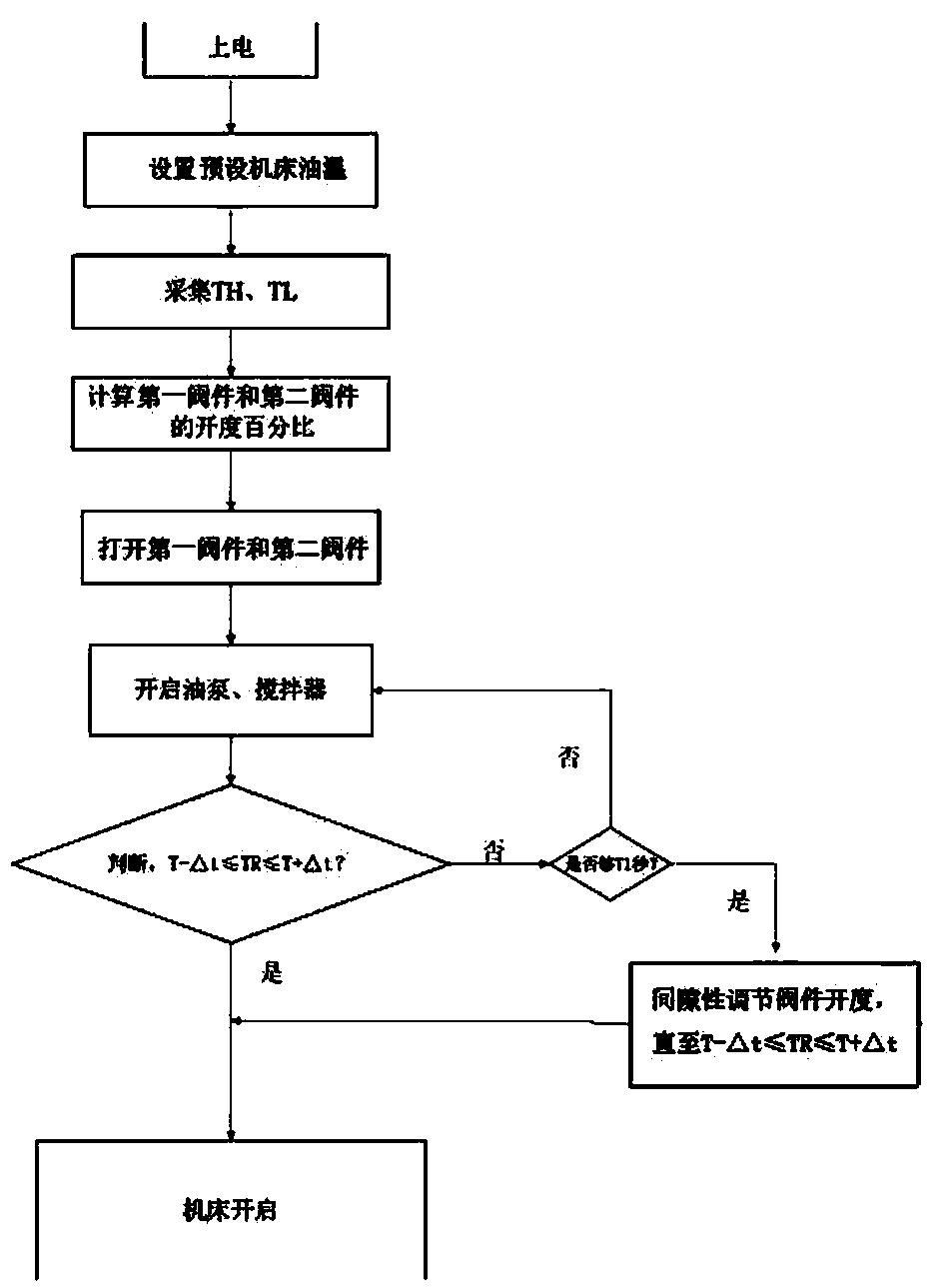

Image

  • Centralized cooling oil cooling unit and control method
  • Centralized cooling oil cooling unit and control method
  • Centralized cooling oil cooling unit and control method

Examples


Embodiment Construction

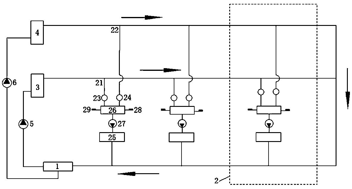
[0040] Such as figure 1 As shown, the preferred embodiment of the present invention proposes an oil cooling unit for centralized cooling, including: a total oil tank 1 and at least two machine tool oil circuits 2, the total oil tank 1 is connected with a first oil temperature regulating device 3 and a second oil temperature regulating device 3 arranged in parallel. Temperature regulating device 4. The first oil temperature adjustment device 3 provides cold oil, and the first oil pump 5 is connected in series between the main oil tank 1 and the first oil temperature adjustment device 3, and the first oil pump 5 sends the oil in the main oil tank 1 to the first oil temperature adjustment device 3 to lower the temperature, and the first oil temperature regulating device 3 controls the outlet oil temperature to the temperature TL. The second oil temperature regulating device 4 provides hot oil, and the second oil pump 6 is connected in series between the total oil tank 1 and the ...


PUM


Abstract

The invention discloses a centralized cooling oil cooling unit and a control method. The centralized cooling oil cooling unit comprises a main oil tank and at least two machine tool oil ways, whereinthe main oil tank is connected with a first oil temperature adjusting device and a second oil temperature adjusting device which are arranged in parallel, and the inlet of each machine tool oil way isprovided with a first oil inlet branch connected with the first oil temperature adjusting device and a second oil inlet branch connected with the second oil temperature adjusting device. The oil cooling unit has the advantages of being low in cost, small in load, high in flexibility and the like.

Description

technical field [0001] The invention relates to the technical field of oil cooling units, in particular to an oil cooling unit for centralized cooling and a control method. Background technique [0002] A production workshop in a large-scale manufacturing enterprise usually gathers a large number of processing machine tools. In order to ensure the stable operation of the machine tools, the traditional method is to equip each machine tool with an oil cooler, which not only requires a large investment of money, but also occupies a large amount of workshop space. During use, a large number of personnel are required to repair, maintain and clean the oil cooler. In addition, the oil cooler for each machine tool will discharge the condensed waste heat to the production workshop, which will greatly increase the air conditioning load of the workshop in summer, resulting in a waste of production costs for the enterprise. [0003] Therefore, how to design an oil-cooled unit for centr...

Claims


Application Information

Patent Timeline
Patent Type & Authority Applications(China)
IPC IPC(8): F25B1/00F25B49/02B23Q11/12
CPCB23Q11/126F25B1/00F25B49/02
Inventor 赵成寅毕增利陈桂福杨爱玲
Owner GREE ELECTRIC APPLIANCES INC
Why Eureka
Eureka Blog
Learn More