A kind of exposure equipment and exposure system

A technology of equipment and abutment, which is applied in the direction of microlithography exposure equipment, photomechanical equipment, and photolithography process exposure equipment, etc., which can solve the problems of bending deformation of the mask plate, uneven distribution of ultraviolet rays, and poor uniformity of line width of exposed products, etc. , to achieve the effect of improving line width uniformity

Active Publication Date: 2022-01-11
BOE TECH GRP CO LTD +1
View PDF8 Cites 0 Cited by
  • Summary
  • Abstract
  • Description
  • Claims
  • Application Information

AI Technical Summary

Problems solved by technology

The mask plate 13 is bent and deformed, resulting in inconsistent gaps between the lower surface of the mask plate 13 and the upper surface of the substrate 12 at different positions on the equipment base 21
In the proximity exposure process of array substrates, the exposure amount, uniformity of illumination and the gap between the lower surface of the mask and the upper surface of the substrate are the main parameters affecting product quality. When the mask at different positions on the equipment base When the gap between the lower surface and the upper surface of the substrate is inconsistent, it will lead to poor line width uniformity of exposed products
For example, in the case of using a negative photoresist, at the position where the distance between the lower surface of the mask plate and the upper surface of the substrate is small, the product line width at the corresponding position will be smaller; Where the distance from the upper surface is large, the line width of the product at the corresponding position will be too large, making the uniformity of the line width of the exposed product poor
[0004] There is no effective solution to the uneven distribution of ultraviolet rays and the bending and deformation of the mask plate. Therefore, it is urgent to solve the problem of poor line width uniformity of exposed products from other angles to improve the quality of exposed products.

Method used


Image

  • A kind of exposure equipment and exposure system
  • A kind of exposure equipment and exposure system
  • A kind of exposure equipment and exposure system

Examples


Embodiment Construction

[0045] In order to make the purpose, technical solution and advantages of the present invention more clear, the embodiments of the present invention will be described in detail below in conjunction with the accompanying drawings. It should be noted that, in the case of no conflict, the embodiments in the present application and the features in the embodiments can be combined arbitrarily with each other.

[0046] The technical content of the present invention will be described in detail below through specific embodiments.

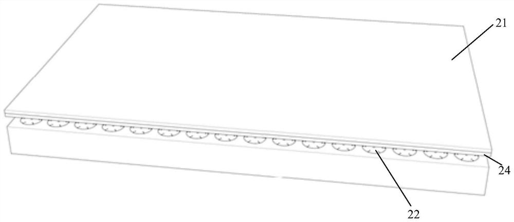
[0047] image 3 It is a schematic structural diagram of an exposure device according to an embodiment of the present invention, Figure 4 for image 3 The schematic diagram of the decomposition mechanism, such as image 3 and Figure 4As shown, the exposure equipment includes a base 23 and a base 21 positioned above the base 23 for carrying the substrate to be exposed. The exposure equipment also includes at least one adjustment device 22 arranged betwee...


PUM


Abstract

The invention discloses an exposure device and an exposure system. The exposure equipment includes a pedestal and a base platform located above the base for carrying the substrate, and it is characterized in that the exposure equipment further includes a base set between the base and the base platform for adjusting the base Curvature or / and temperature adjustment of the table. In this exposure equipment, the curvature or / and temperature of the base platform can be adjusted through the adjustment device, so that the curvature of the surface of the base platform is consistent with the bending deformation of the mask plate, so that the curvature of the substrate to be exposed will also be consistent with the curvature of the mask plate The deformation phase is consistent, so that the gap between the lower surface of the mask plate at different positions and the upper surface of the substrate is consistent; or / and, the temperature at different positions of the base can be adjusted through the adjustment device, so that the temperature at different positions of the substrate remains consistent, thereby improving exposure Linewidth uniformity at different locations on the substrate.

Description

technical field [0001] The invention relates to the field of display technology, in particular to an exposure device and an exposure system. Background technique [0002] In the manufacturing process of the display panel, a mask exposure process is often required. figure 1 It is a schematic diagram of the optical path of the proximity exposure equipment. In the actual mask exposure process, such as in proximity exposure equipment, such as figure 1 As shown, the illuminance distribution of the ultraviolet light projected on the equipment base from the high-pressure mercury lamp is uneven, and with the prolongation of the high-pressure mercury lamp, the illuminance distribution of the ultraviolet light projected on the equipment base also changes with time , resulting in a large difference in line width at different positions of the exposed product, and poor line width uniformity. [0003] In addition, in the mask exposure process, the bending deformation of the mask plate ...

Claims


Application Information

Patent Timeline
Patent Type & Authority Patents(China)
IPC IPC(8): G03F7/20
CPCG03F7/20G03F7/70716G03F7/70858G03F7/7095
Inventor 向琛陈轶
Owner BOE TECH GRP CO LTD
Why Eureka
Try Eureka