
Flexible retention systems for portable electronic devices

A technology for holding systems and electronic devices, applied in the direction of locking portable objects, tables, applications, etc., and can solve problems such as falling objects

Active Publication Date: 2019-10-11
ERGOTRON
View PDF20 Cites 0 Cited by
  • Summary
  • Abstract
  • Description
  • Claims
  • Application Information

AI Technical Summary

Problems solved by technology

In another example, a user may inadvertently interact with an object, causing the object to fall from the work surface

Method used


Image

  • Flexible retention systems for portable electronic devices
  • Flexible retention systems for portable electronic devices
  • Flexible retention systems for portable electronic devices

Examples


Embodiment Construction

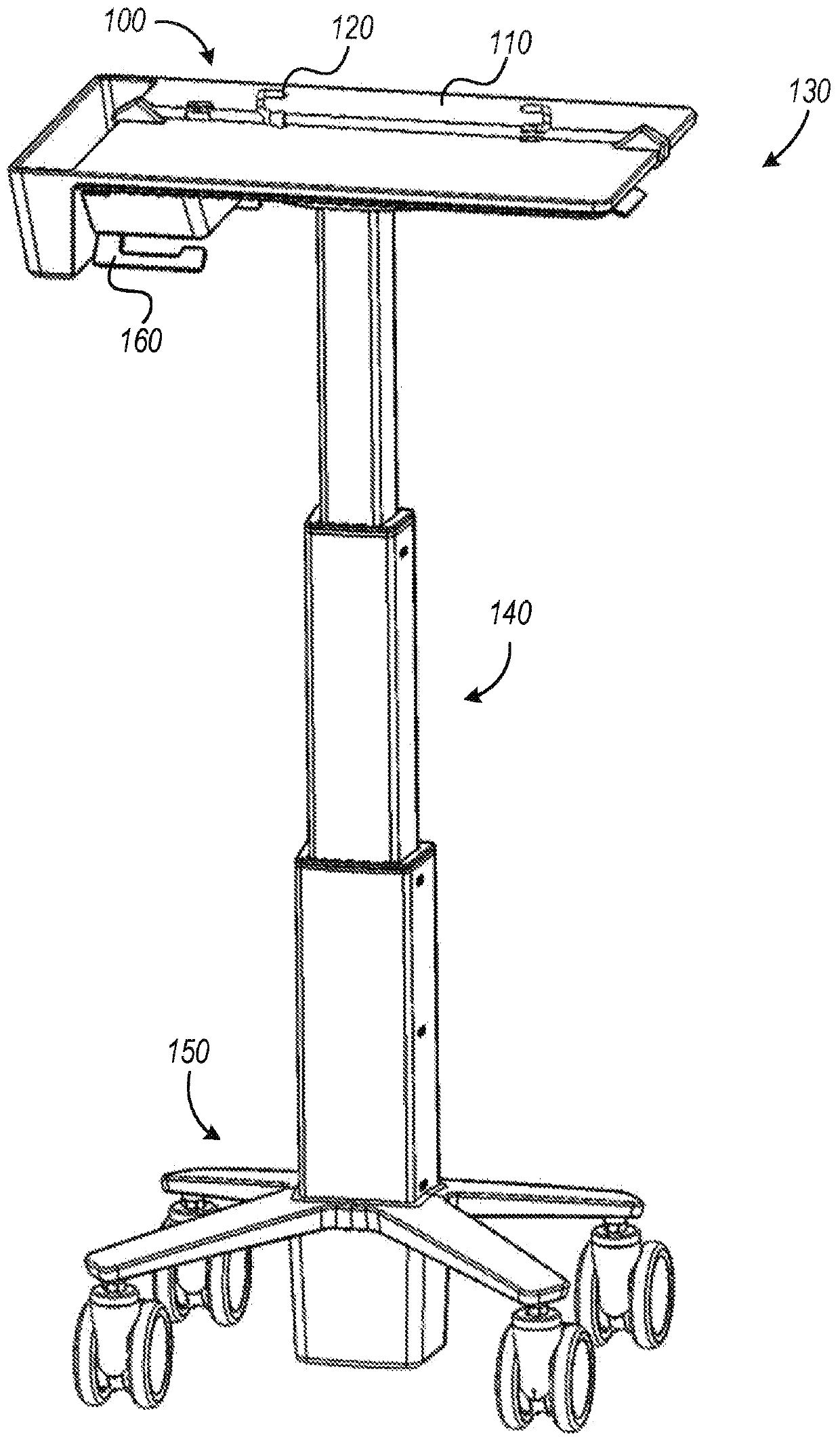
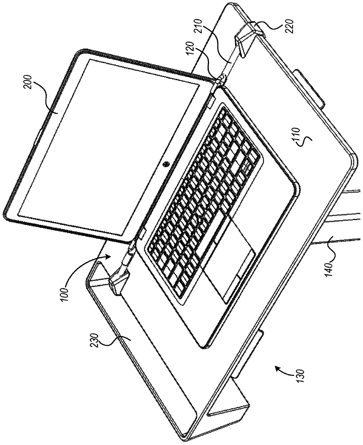
[0022] figure 1 A perspective view of one example of a retention system 100 and a height-adjustable work surface 110 is shown. Retention system 100 may include at least one device clip 120 . The device clip 120 may be adapted to engage with a portion (eg, an edge, a hinge, etc.) of the portable electronic device on the work surface 110 .

[0023] The work surface 110 may form part of a cart 130 . The cart 130 may include a riser 140 and may include a wheeled base 150 . The work surface 110 may be coupled to a riser 140 . Lifter 140 may be coupled to wheeled base 150 . Lift 140 may be adapted to raise and lower work surface 110 (eg, relative to wheeled base 150 ). The cart 130 may include a handle 160 adapted to engage and disengage the lock and thereby allow the work surface 110 to be raised and lowered. Wheeled base 150 may be adapted (eg, by coupling wheels to wheeled base 150 ) to allow riser 140 and work surface 110 to translate relative to a substrate (eg, a floor o...


PUM


Abstract

A retention system for securing a portable electronic device to the work surface can include an elongated member. The elongated member can be adapted to couple with a work surface. The retention system can include a device clip. The device clip can be coupled to the elongated member. The device clip can be slidably engaged with the elongated member. The device clip can be adapted to engage with anedge of the portable electronic device located on the work surface.

Description

[0001] Cross References to Related Applications [0002] This patent application claims priority to U.S. Provisional Patent Application No. 62 / 469,138, filed March 9, 2017, by Theis et al., entitled "Flexible Retention Systems for Portable Electronic Devices," which is hereby incorporated by reference in its entirety. technical field [0003] This document relates generally, but not exclusively, to retention systems for portable electronic devices. Background technique [0004] A work surface may be provided for supporting an object, such as a portable electronic device (eg, laptop, tablet, e-reader, convertible laptop, smartphone, etc.). In some cases, the work surface is articulable (eg, the work surface is repositionable). The articulation of the work surface may allow the object to fall from the work surface, and the drop can damage the object. In another example, a user may inadvertently interact with an object, causing the object to fall from the work surface. Cont...

Claims


Application Information

Patent Timeline
IPC IPC(8): F16M11/04E05B73/00F16M11/28F16M11/42F16M13/00A47B23/04F16G11/02F16G11/14
CPCA47B23/042E05B73/0005E05B73/0082F16M11/041F16M11/28F16M11/42F16G11/025F16M13/00F16G11/14A47B21/04A47B21/02F16B2/22
Inventor J·W·泰斯M·J·马伦J·J·贝塞尔S·S·阿萨马瑞T·C·D·王
Owner ERGOTRON
Learn More