

Anaerobic microorganism separation device
An anaerobic microorganism and separation device technology, which is applied in the field of microbial separation device, can solve the problems of affecting the separation effect of anaerobic microorganisms, difficulty in uniform coating of medium, time-consuming and labor-intensive manual rolling tubes, etc., so as to facilitate rapid coagulation and avoid Effect of uneven coating and reduced bottom area
- Summary
- Abstract
- Description
- Claims
- Application Information
AI Technical Summary
Problems solved by technology
Method used
Image

Examples
Embodiment 1
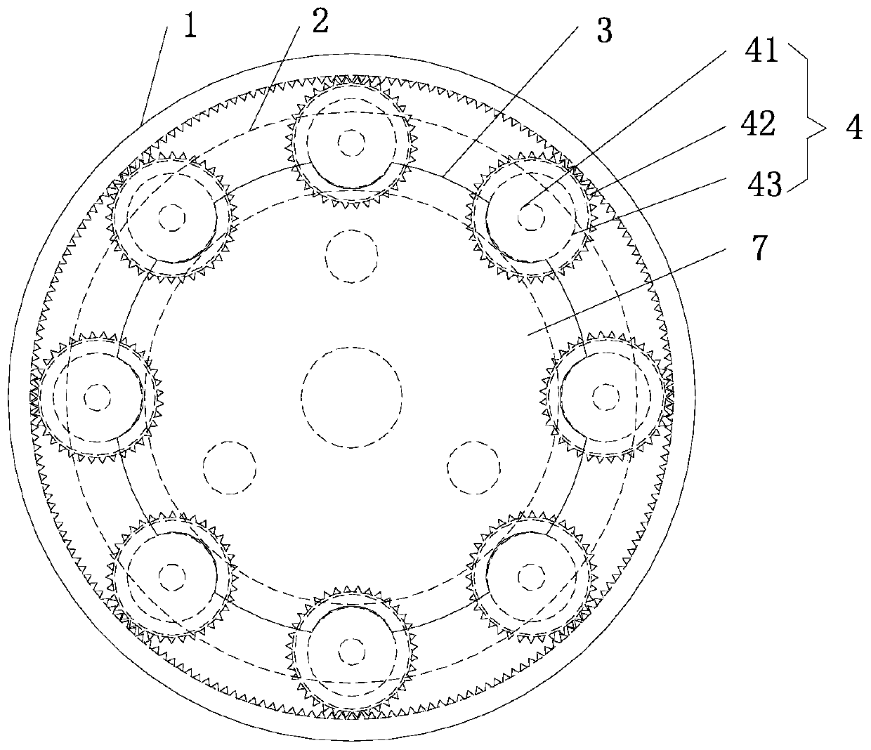
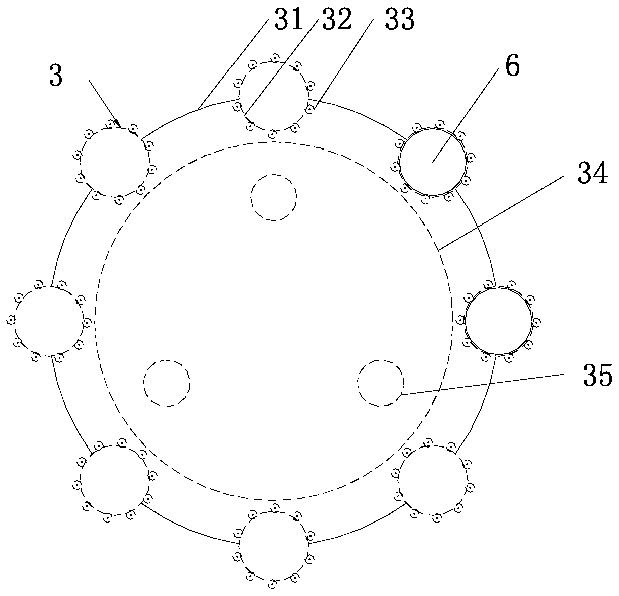
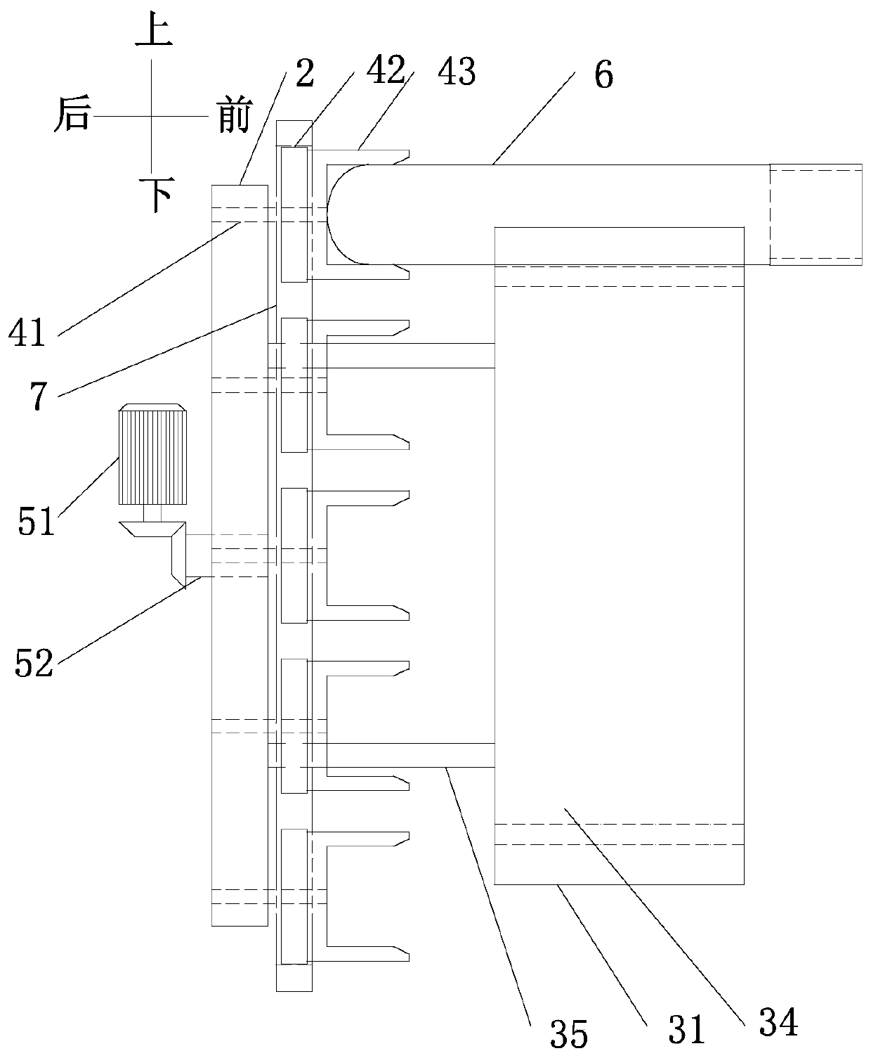
[0030] Such as figure 1 , figure 2 , Figure 7 As shown, a device for separating anaerobic microorganisms includes a housing 1, several test tube rotating assemblies 4 that are rotatably assembled in the housing 1, a test tube support frame 3 for supporting anaerobic test tubes 6 adapted to the test tube rotating assembly 4, A relative rotation assembly capable of relative rotation to drive the test tube rotation assembly 4 to rotate, a drive motor 51 for driving the components in the relative rotation assembly to move relative to each other, and an ice chamber arranged in the casing 1;
[0031] The test tube rotation assembly 4 includes a "concave" test tube holder 43 for clamping the bottom of the anaerobic test tube 6, an assembly runner 42 coaxially arranged with the test tube holder 43, and a test tube holder 43 coaxially installed on the assembly runner. Component rotating shaft 41 on 42, relatively rotating component drives test tube rotating component 4 to rotate th...
Embodiment 2
[0037] This embodiment is another implementation based on the embodiment 1, the description of the same technical solutions as the embodiment 1 will be omitted, and only the technical solutions different from the embodiment 1 will be described.
[0038] In this embodiment, a method of rotating an anaerobic test tube is specifically described.
[0039] Such as Figure 1 to Figure 3 As shown, the relative rotation assembly includes a first driving wheel 2 and a second driving gear ring 7, wherein the first driving wheel 2 rotates under the drive of the driving motor 51, and the second driving gear ring 7 is fixedly connected to the shell 1 One side; the first driving runner 2 is used as a driving part, specifically, the first driving runner 2 is a gear, the first driving runner 2 is assembled in the housing 1 through bearing rotation, and the second driving gear ring 7 is arranged on the first The outer circumference of the drive runner 2 and meshes with the first drive runner ...
Embodiment 3
[0044] This embodiment is another implementation based on embodiment 1, and the description of the same technical solution as in embodiment 1 will be omitted; in this embodiment, a kind of rotation mode of anaerobic test tube different from that in embodiment 2 is specifically listed .
[0045] Such as figure 1 , figure 2 and Figure 4 As shown, the relative rotation assembly includes the first driving wheel 2 and the second driving gear ring 7, wherein, unlike embodiment 2, in this embodiment 3, the driving motor 51 drives the second driving gear ring to rotate, that is, the second driving The gear ring is used as a driving part, and the first driving wheel 2 is fixed; specifically, the second driving gear ring 7 is rotatably assembled in the housing 1 through a bearing, and the relative rotation assembly also includes a The first driving wheel 2 and the component rotating shaft 41 are arranged in an annular array with the rotation axis of the second driving gear ring 7 a...
PUM
 Abstract
Description
Claims
Application Information