Laser shock prediction method based on laser fluctuation and surface laser light scattering and device

A technology of laser scattering and laser shock, applied in the direction of measuring devices, optical devices, laser welding equipment, etc., can solve problems such as unevenness, increased surface roughness, scrapped parts, etc., and achieve the effect of uniform roughness

Inactive Publication Date: 2019-10-15
GUANGDONG LASER PEENING TECH CO LTD +2
View PDF10 Cites 3 Cited by
  • Summary
  • Abstract
  • Description
  • Claims
  • Application Information

AI Technical Summary

Problems solved by technology

Laser shock strengthening will inevitably increase the surface roughness during the processing of the blade, and the increase in the surface roughness of the blade will weaken the mechanical properties of the blade, which will greatly reduce the safety, reliability and fatigue strength of the aero-engine.
In addition, it is impossible to observe the change of the surface morphology of the part during the impact process, and after the impact is over, the surface of the part is difficult to repair, resulting in the scrapping of the part
[0003] The existing technology can only use flat-hat beam laser to impact, and the laser energy myopia is considered as uniform distribution. Although compared with Gaussian beam, flat-hat beam has more advantages for laser peening, but the spatial distribution of laser energy of flat-hat beam Still very uneven, resulting in extremely poor and uneven surface roughness of the part after impact

Method used


Image

  • Laser shock prediction method based on laser fluctuation and surface laser light scattering and device
  • Laser shock prediction method based on laser fluctuation and surface laser light scattering and device
  • Laser shock prediction method based on laser fluctuation and surface laser light scattering and device

Examples


Embodiment Construction

[0020] The following will clearly and completely describe the technical solutions in the embodiments of the present invention with reference to the accompanying drawings in the embodiments of the present invention. Obviously, the described embodiments are only some, not all, embodiments of the present invention. Based on the embodiments of the present invention, all other embodiments obtained by persons of ordinary skill in the art without making creative efforts belong to the protection scope of the present invention.

[0021] The technical solutions of the present invention will be further described below in conjunction with specific examples.

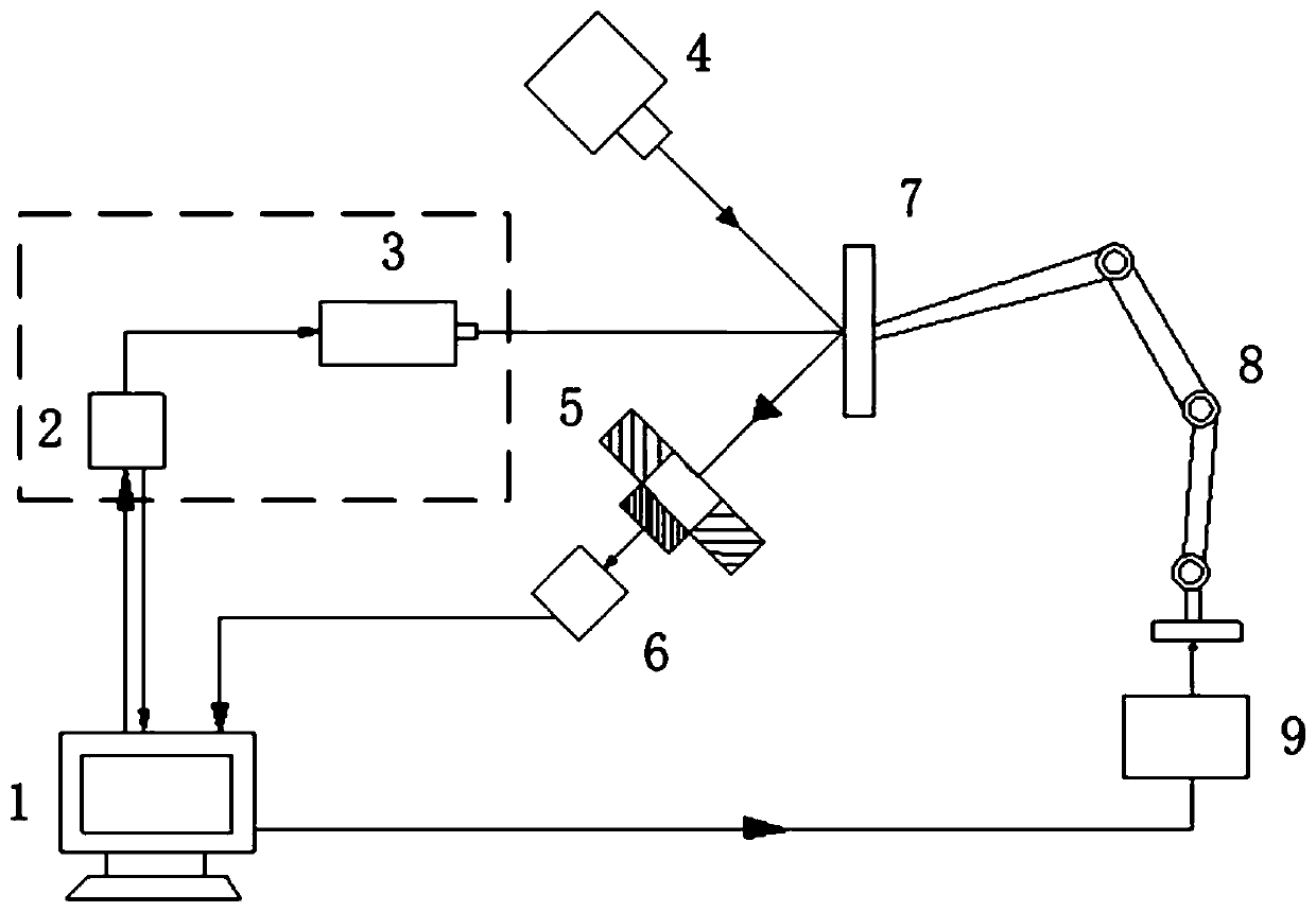
[0022] A laser shock prediction method based on laser fluctuations and surface laser scattering, comprising the following steps:

[0023] Step 1: Use the laser scattering measurement method to measure the original surface roughness data of the part 7, and import the data into the computer 1 through the laser data collector 2. The str...


PUM


Abstract

The purpose of the invention is to provide a laser shock prediction method based on laser fluctuation and surface laser light scattering and a device. The surface roughness of a part after impact is predicted through laser energy spatial distribution data measured in real time to set laser device input parameters; and the data of the surface roughness variation of the part is measured in real timethrough a laser scattering measurement method to correct the laser device input parameters in real time, so that the part finally meets the design requirements. The invention also discloses a laser shock reinforcing device based on the laser beam parameter fluctuation and part surface laser scattering measurement data, which comprises a computer, a laser shot blasting device, a part robot, a partrobot controller, a measuring laser device, a detector, and an information collecting system. The laser shock reinforcing device based on the laser beam parameter fluctuation and the part surface laser scattering measurement data can perform laser shot blasting through the real-time variation of the laser energy data and the change of the surface roughness data of the part to improve the surfaceprecision.

Description

technical field [0001] The invention relates to the field of mechanical manufacturing, in particular to a device based on a laser shock prediction method based on laser fluctuations and surface laser scattering. Background technique [0002] Aeroengines are known as the "Flower of Industry". The engine blade is its core. The aero-engine is a typical high-precision, variable-section thin-walled part. Its quality directly determines the safety and reliability of the aero-engine. Laser shock peening will inevitably increase the surface roughness during the processing of the blade, and the increase in the surface roughness of the blade will weaken the mechanical properties of the blade, which will greatly reduce the safety, reliability and fatigue strength of the aero-engine. In addition, it is impossible to observe the change of the surface morphology of the part during the impact process, and after the impact is over, the surface of the part is difficult to repair, resulting ...

Claims


Application Information

Patent Timeline
IPC IPC(8): G01B11/30B23K26/356
CPCB23K26/356G01B11/30
Inventor 张永康刘迎春单晓明张驰郭小军林超辉
Owner GUANGDONG LASER PEENING TECH CO LTD
Why Eureka
Try Eureka