Modulatable CT detector data compression and acquisition mode

A data compression and detector technology, applied in image data processing, radiological diagnostic equipment, radiological diagnostic image/data processing, etc., can solve the problems of reducing data bandwidth, fixed area division, large data bandwidth occupation, etc., to achieve Reduced requirements and the effect of reducing the bandwidth occupation of the slip ring

Active Publication Date: 2019-10-15
四川明峰医疗科技有限公司
View PDF7 Cites 2 Cited by
  • Summary
  • Abstract
  • Description
  • Claims
  • Application Information

AI Technical Summary

Problems solved by technology

Therefore, due to the limitation of the slip ring bandwidth, it is difficult to achieve fast scanning, flying focus switching and kV switching at the same time on cardiac scanning
In the prior art, multi-channel coupling is usually used to reduce the data bandwidth, but the area division is fixed, and this multi-channel method will reduce the resolution of the entire scanning area
In the existing technology, the sampling rate in the angular direction is also increased to reduce the aliasing artifacts caused by the large sampling distance in the off-center area. This technology will further increase the occupation of data bandwidth.

Method used


Image

  • Modulatable CT detector data compression and acquisition mode
  • Modulatable CT detector data compression and acquisition mode
  • Modulatable CT detector data compression and acquisition mode

Examples


Embodiment 1

[0027] A modulable CT detector data compression acquisition method of the present embodiment includes the following:

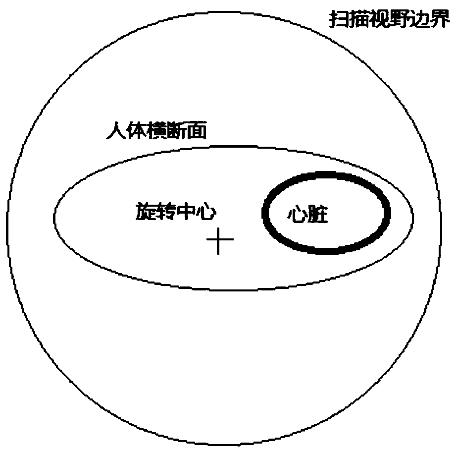
[0028] (1) Patient orientation scans are performed; the patient's supine position on the scanning bed and the orientation slice images are collected for subsequent calculations. The CT system estimates the area of ​​the heart based on the positioning film and the patient's lying position on the scanning table.

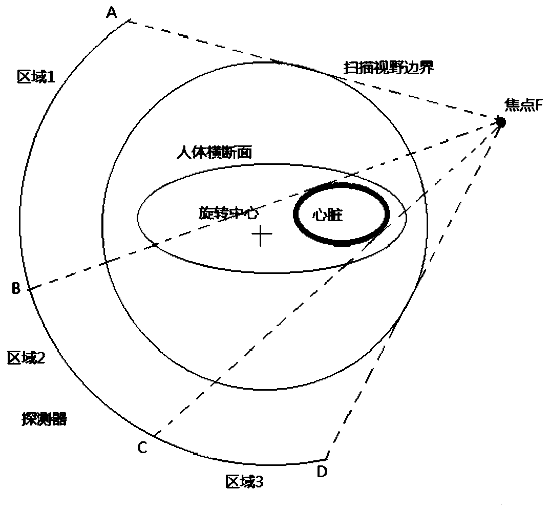
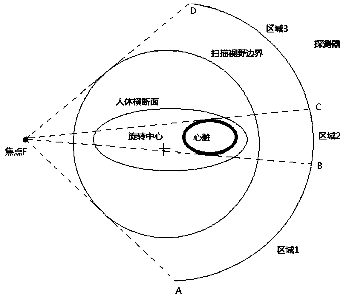
[0029] (2) Multiple scanning areas are dynamically divided according to the rotation of the gantry: the multiple scanning areas include area 1, area 2 and area 3; the area formed by the intersection of the focal point and the cardiac scanning area with the detector is area 2, and the focus and The tangent of the cardiac scanning area intersects with the detector and the tangent of the focal point and the boundary of the scanning field of view intersects with the detector to form area 1 and area 3; as the gantry rotates, the sizes of the three areas cha...

Embodiment 2

[0037] A modulable CT detector data compression acquisition method of the present embodiment includes the following:

[0038] (1) Patient orientation scans are performed; the patient's supine position on the scanning bed and the orientation slice images are collected for subsequent calculations. The CT system estimates the area of ​​the heart based on the positioning film and the patient's lying position on the scanning table.

[0039](2) Multiple scanning areas are dynamically divided according to the rotation of the gantry: the multiple scanning areas include area 1, area 2 and area 3; the area formed by the intersection of the focal point and the cardiac scanning area with the detector is area 2, and the focus and The tangent of the cardiac scanning area intersects with the detector and the tangent of the focal point and the boundary of the scanning field of view intersects with the detector. The area ranges are area 1 and area 3; as the gantry rotates, the sizes of the thr...


PUM


Abstract

The invention provides a modulatable CT detector data compression and acquisition mode, and relates to the technical field of medical images. The mode comprises the steps: carrying out the scanning ofa patient positioning film; performing dynamic dividing of a plurality of scanning areas according to the rotation of a rack, wherein the plurality of scanning areas comprise a first area, a second area and a third area, an area range formed by intersecting the tangent lines of the focus and the heart scanning area in a detector is the second area, an area range formed by intersecting the tangentlines of the focus and the heart scanning area in the detector and intersecting the tangent lines of the focus and the scanning view boundary in the detector is the first area and the third area, andthe sizes of the three areas are dynamically changed along with the rotation of the rack; and dynamically compressing the data of the first and third areas, wherein the compression process is completed on a data acquisition board of a rotor part of a CT machine. The data compression and acquisition mode can reduce the data bandwidth, control the data volume and reduce the requirement of the slipring data transmission bandwidth.

Description

technical field [0001] The invention relates to the technical field of medical equipment, in particular to a modulating CT detector data compression acquisition method. Background technique [0002] The main components of the third-generation CT system include Tube (ball tube), Collimator (beam limiter), and Detector (detector). The X-ray tube emits X-rays, which are limited by a beam limiter to form a cone-shaped beam. The cone-shaped light beam is irradiated on the detector and converted into an electrical signal by the detector, and then converted into digital information by the data acquisition and conversion unit and stored in the image processing system. The image processing system generates images and displays them on the monitor through a series of correction algorithms and image reconstruction algorithms. In terms of cost and technology maturity, mainstream detectors use many detector modules arranged on an arc or polygonal surface to form the entire detector. A ...

Claims


Application Information

Patent Timeline
Patent Type & Authority Applications(China)
IPC IPC(8): G16H30/20G06T9/00A61B6/03A61B6/00
CPCG16H30/20G06T9/00A61B6/032A61B6/52A61B6/503G06T2207/10081
Inventor 王斌王瑶法徐亦飞黄俊杰刘骅
Owner 四川明峰医疗科技有限公司
Why Eureka
Try Eureka