Foil stamping die

A technology for stamping dies and foils, applied in forming tools, manufacturing tools, metal processing equipment, etc., can solve the problems that foils are not easy to fix, easily deviate from molds, affect processing shape requirements and processing accuracy requirements, etc.

Active Publication Date: 2019-10-18
江苏全成奥马热工科技有限公司
View PDF11 Cites 2 Cited by
  • Summary
  • Abstract
  • Description
  • Claims
  • Application Information

AI Technical Summary

Problems solved by technology

[0004] In order to make up for the deficiencies of the existing technology, to solve the problems in the prior art that the foil material is not easy to fix, easily deviate from the mold, affect the processing shape requirements and processing accuracy requirements in the processing process, and make the processed foil material not meet the requirements, this paper An elastic coupling proposed by the invention

Method used


Image

  • Foil stamping die
  • Foil stamping die
  • Foil stamping die

Examples


Embodiment approach

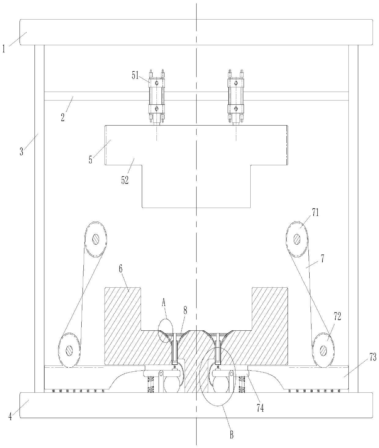
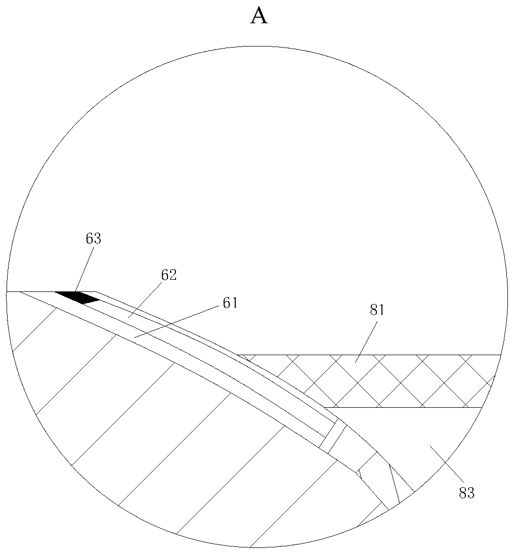
[0024]As an embodiment of the present invention, an air groove 61 is provided on the side wall of the lower die unit 6 around the suction cup 81; a sealing strip 62 is arranged in the air groove 61; The cooperation of 7 pushes the push rod 82 to move up, thereby extruding the gas in the cavity 83, so that the sealing strip 62 is pressed and slides out along the air groove 61, and plays a sealing effect around the suction cup 81, and enhances the adsorption effect of the suction cup 81; When working, when the push plate 73 squeezes one end of the top plate 74 to make the other end of the top plate 74 tilt, it will push the push rod 82 to move upward, thereby squeezing the gas in the cavity 83, and most of the gas plays the role of ejecting the suction cup 81 , and a part of the gas squeezes the sealing strip 62 through the air groove 61, so that the sealing strip 62 slides out from the air groove 61, thereby sealing the surrounding of the suction cup 81, enhancing the adsorption...


PUM


Abstract

The invention relates to the technical field of stamping dies, in particular to a foil stamping die. The foil stamping die comprises a cover plate, a fixed plate, support plates, a bottom plate, an upper stamping die unit, a lower stamping die unit, driving units and adsorption units. The upper ends of the support plates are connected with the lower end face of the cover plate. The lower ends of the support plates are connected with the upper end face of the bottom plate. The two ends of the fixed plate are connected with the two inner side faces of the support plates. The upper stamping die unit comprises cylinders and an upper die plate. The cylinders are fixed to the fixed plate. The output ends of the cylinders are connected with the upper end face of the upper die plate. The lower stamping die unit is fixed to the upper end face of the bottom plate. Each driving unit comprises a gear I, a gear II, a push plate and a top plate. The adsorption units are embedded into the upper surface of the lower stamping die unit. The cylinders, the upper die plate and the driving units cooperate to drive the adsorption units to adsorb foil to be stamped.

Description

technical field [0001] The invention relates to the technical field of stamping dies, in particular to a foil stamping die. Background technique [0002] Stamping die is a special process equipment for processing materials (metal or non-metal) into parts (or semi-finished products) in cold stamping processing, called cold stamping die (commonly known as cold stamping die); the use of foil is very wide, this It is determined by the characteristics of the foil metal and the foil itself; for example, steel and alloy foils are mainly used in electronics, aerospace, instrumentation and other departments; iron-nickel soft magnetic alloy foils are used to make miniature high-frequency pulse transformers, switch coils , magnetic recorder, magnetic amplifier, etc.; titanium alloy foil is used to make decorative nets on jet engine combustion tubes, metal composite heat-resistant tiles and titanium multi-layer walls in space shuttle heat-proof systems; tungsten-molybdenum and other foi...

Claims


Application Information

Patent Timeline
Patent Type & Authority Applications(China)
IPC IPC(8): B21D33/00B21D37/12B21D45/04
CPCB21D33/00B21D37/12B21D45/04
Inventor 沈恒祥周洋洋朱城
Owner 江苏全成奥马热工科技有限公司
Why Eureka
Try Eureka