A heater protective cover welding aid

A protective cover and heater technology, applied in welding/cutting auxiliary equipment, welding equipment, auxiliary devices, etc., can solve the problems of reducing discomfort and people's discomfort, and achieve the effects of reducing trouble, shortening welding time, and facilitating welding

Active Publication Date: 2021-03-02
江苏浦贝智能科技有限公司
View PDF9 Cites 0 Cited by
  • Summary
  • Abstract
  • Description
  • Claims
  • Application Information

AI Technical Summary

Problems solved by technology

[0003] In order to overcome the disadvantages that people will feel uncomfortable when welding for a long time, need other people to assist welding, and need to constantly adjust the position when welding, the technical problem to be solved is to provide a standing welding that reduces discomfort and does not require welding. Heater shield welding aid for other person assistance and reduced number of moves

Method used


Image

  • A heater protective cover welding aid
  • A heater protective cover welding aid
  • A heater protective cover welding aid

Examples


Embodiment 1

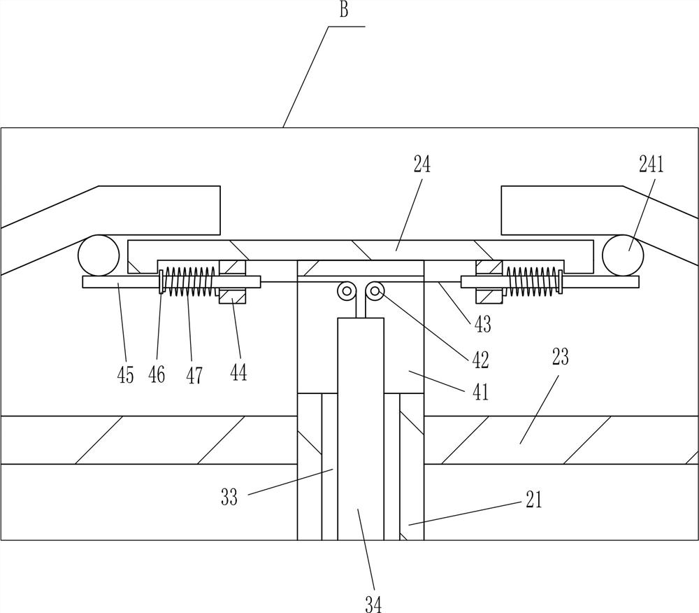
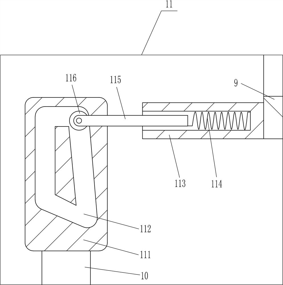
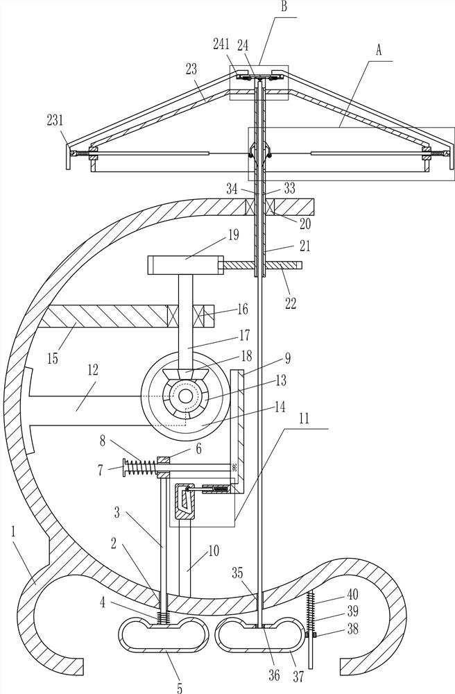
[0017] A heater shield welding aid such as Figure 1-2 As shown, it includes a first bracket 1, a guide rod 3, a first spring 4, a first pedal 5, a first sliding sleeve 6, a first sliding rod 7, a second spring 8, a rack 9, and a first rod 10 , rail device 11, support plate 12, first bevel gear 13, first gear 14, second bracket 15, first bearing 16, first rotating shaft 17, second bevel gear 18, second gear 19, second bearing 20 , the second rotating shaft 21, the third gear 22, the placement disc 23 and the support plate 24, the left side of the first support 1 bottom has the first guide hole 2, and the first guide hole 2 is movable with a guide rod 3, and the guide rod 3 The lower part is wound with a first spring 4, the upper end of the first spring 4 is connected with the first bracket 1, the lower end of the guide rod 3 is provided with a first pedal 5, the first pedal 5 is located at the lower part of the first bracket 1, and the upper end of the guide rod 3 is provided ...

Embodiment 2

[0019] A heater shield welding aid such as Figure 1-2As shown, it includes a first bracket 1, a guide rod 3, a first spring 4, a first pedal 5, a first sliding sleeve 6, a first sliding rod 7, a second spring 8, a rack 9, and a first rod 10 , rail device 11, support plate 12, first bevel gear 13, first gear 14, second bracket 15, first bearing 16, first rotating shaft 17, second bevel gear 18, second gear 19, second bearing 20 , the second rotating shaft 21, the third gear 22, the placement disc 23 and the support plate 24, the left side of the first support 1 bottom has the first guide hole 2, and the first guide hole 2 is movable with a guide rod 3, and the guide rod 3 The lower part is wound with a first spring 4, the upper end of the first spring 4 is connected with the first bracket 1, the lower end of the guide rod 3 is provided with a first pedal 5, the first pedal 5 is located at the lower part of the first bracket 1, and the upper end of the guide rod 3 is provided w...

Embodiment 3

[0022] A heater shield welding aid such as Figure 1-3 As shown, it includes a first bracket 1, a guide rod 3, a first spring 4, a first pedal 5, a first sliding sleeve 6, a first sliding rod 7, a second spring 8, a rack 9, and a first rod 10 , rail device 11, support plate 12, first bevel gear 13, first gear 14, second bracket 15, first bearing 16, first rotating shaft 17, second bevel gear 18, second gear 19, second bearing 20 , the second rotating shaft 21, the third gear 22, the placement disc 23 and the support plate 24, the left side of the first support 1 bottom has the first guide hole 2, and the first guide hole 2 is movable with a guide rod 3, and the guide rod 3 The lower part is wound with a first spring 4, the upper end of the first spring 4 is connected with the first bracket 1, the lower end of the guide rod 3 is provided with a first pedal 5, the first pedal 5 is located at the lower part of the first bracket 1, and the upper end of the guide rod 3 is provided ...


PUM


Abstract

The invention relates to a welding aid, in particular to a welding aid for a heater protective cover. Technical problem to be solved: to provide a heater shield welding aid that can stand up for welding to reduce discomfort, do not require assistance from others, and reduce the number of movements. The technical scheme is: a heater protective cover welding aid, comprising a first bracket, a guide rod, a first spring, a first pedal, a first sliding sleeve, a first sliding rod, a second spring, a rack, a first Support rod, guide rail device, etc.; a first guide hole is opened on the left side of the lower part of the first bracket, a guide rod is movable in the first guide hole, a first spring is wound around the lower part of the guide rod, and the upper end of the first spring is connected with the first bracket . In the present invention, the protective cover can be supported by the provided first bracket, the fifth sliding rod and the support block, and people can perform welding while standing, which reduces the fatigue level of people, and at the same time, it is more convenient for people to carry out welding operations, which is beneficial to improve the performance of people. improve work efficiency and shorten welding time.

Description

technical field [0001] The invention relates to a welding auxiliary device, in particular to a welding auxiliary device for a protective cover of a heater. Background technique [0002] In the cold winter, in order to maintain the temperature in the working space and make people have a good working environment, people often take some heating measures. Using a heater is a more common heating method. In order to make the heater safer and reduce people's electric shock and the chance of burns. During the manufacturing process of the heater, a protective cover will be installed on the front side of the heater to protect people. At present, when people weld the protective cover, they usually squat or bend over to operate. After a long time, people's legs and waist will be sore, which is not conducive to people's welding work; the protective cover is composed of two iron rings and several iron bars, and people need to weld the iron bars on the two iron rings respectively In the p...

Claims


Application Information

Patent Timeline
Patent Type & Authority Patents(China)
IPC IPC(8): B23K37/04
CPCB23K37/0443B23K2103/02
Inventor 不公告发明人
Owner 江苏浦贝智能科技有限公司
Why Eureka
Try Eureka