
Automatic powder feeding device of 3D printer

A technology of 3D printer and powder feeding device, which is applied in the field of 3D printing to achieve the effect of facilitating the detection range, saving materials, and improving the accuracy of powder feeding

Inactive Publication Date: 2019-10-18
BEIJING XINGHANG MECHANICAL ELECTRICAL EQUIP
View PDF6 Cites 7 Cited by
  • Summary
  • Abstract
  • Description
  • Claims
  • Application Information

AI Technical Summary

Problems solved by technology

[0005] The invention proposes a 3D printer automatic powder feeding device to solve the technical problem of how to realize powder feeding automation

Method used


Image

  • Automatic powder feeding device of 3D printer
  • Automatic powder feeding device of 3D printer
  • Automatic powder feeding device of 3D printer

Examples


Embodiment Construction

[0029] In order to make the purpose, content and advantages of the present invention clearer, the specific implementation manners of the present invention will be further described in detail below in conjunction with the accompanying drawings and embodiments.

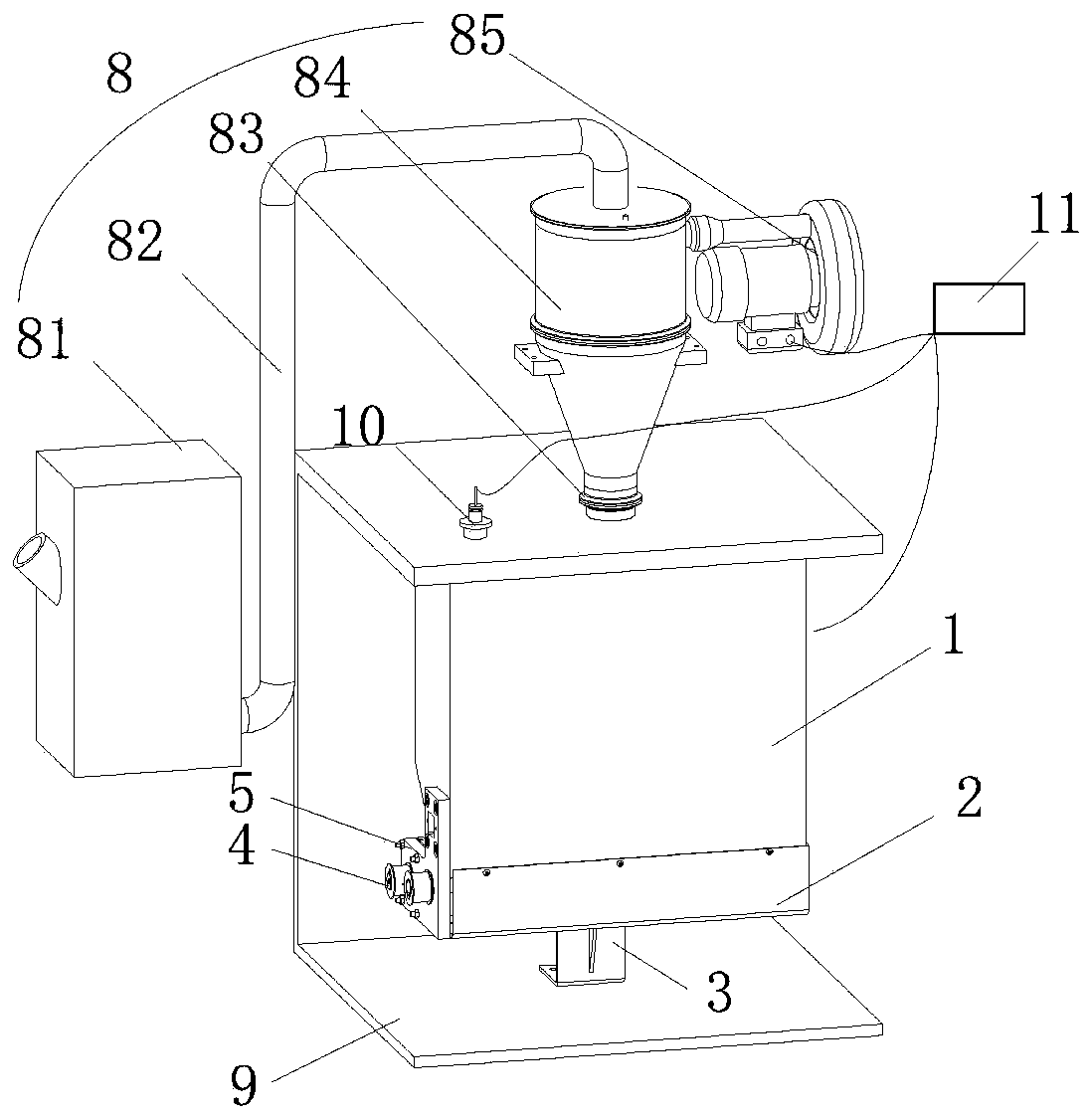
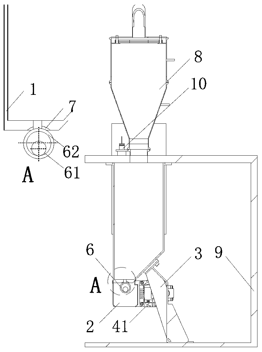
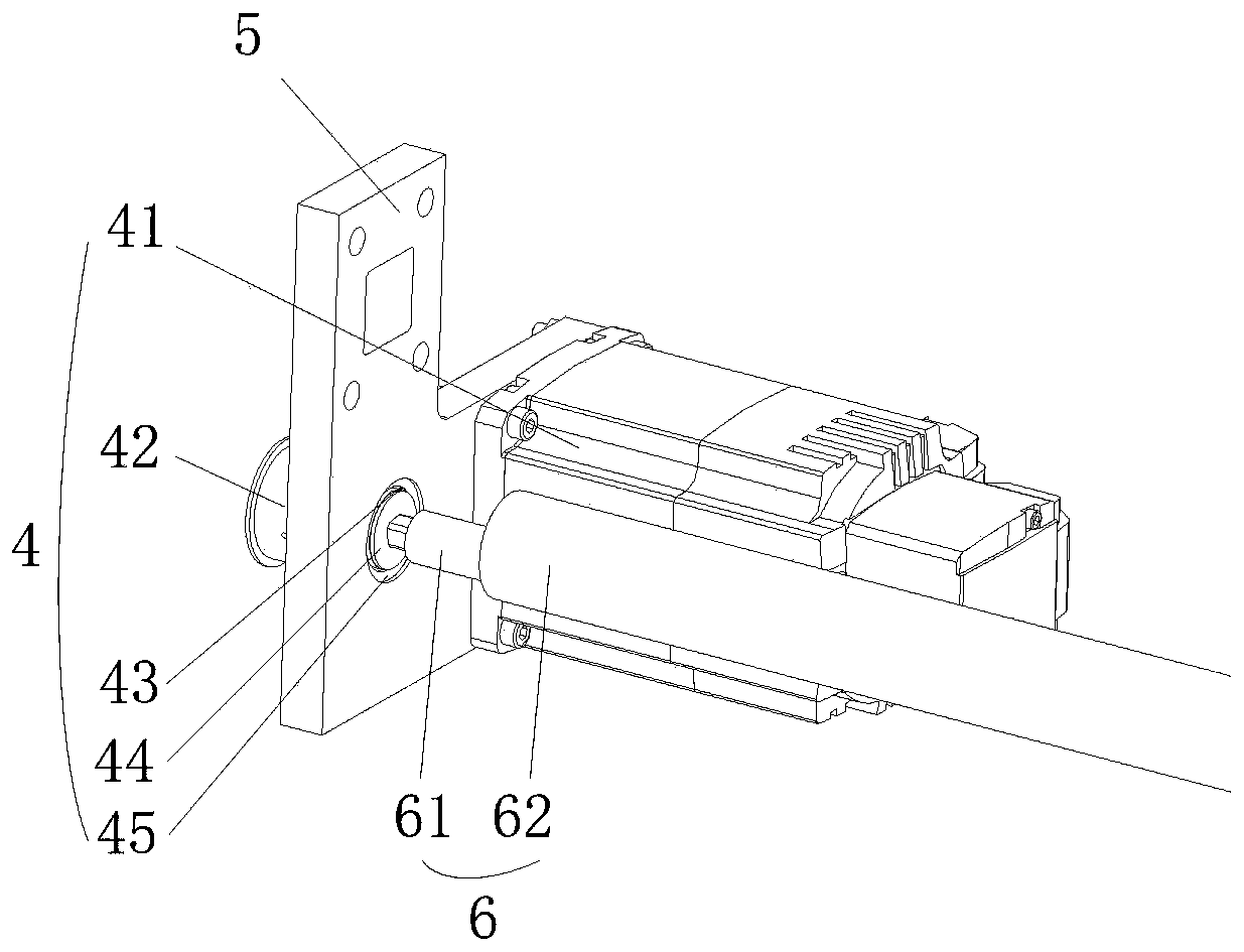
[0030] This embodiment proposes a 3D printer automatic powder feeding device, its structure is as follows figure 1 and 2 shown. The upper powder feeding device includes a powder box 1, a powder retaining cover 2, a bracket 3, a transmission mechanism 4, an L-shaped plate 5, an eccentric shaft 6, a sealing gasket 7, a powder feeding mechanism 8, a molding chamber 9, a material level sensor 10 and a control Device 11. Among them, the powder box 1 is a thin-walled structure, with two rows of bolt connection holes on the top, and is fixed on the top plate of the molding chamber 9 through bolt connection. Through various gaps, a gasket 7 is provided between the powder box 1 and the top plate of the molding chamber 9 to pl...


PUM


Abstract

The invention belongs to the technical field of 3D printing, and particularly relates to an automatic powder feeding device of a 3D printer. The automatic powder feeding device comprises a powder box,a powder blocking cover, a bracket, a transmission mechanism, a L-shaped plate, an eccentric shaft, a sealing pad, a powder feeding mechanism, a forming chamber, a material level sensor and a controller. According to the automatic powder feeding device, the eccentric shaft is arranged, so when the eccentric shaft does periodic motion, power periodically leaks at the lower side of the powder box,in this way, the amount of powder leakage can be controlled, and the structure can be simplified; and meanwhile, through the design of the material level sensor, the controller and the powder feedingmechanism, automatic powder feeding can be achieved.

Description

technical field [0001] The invention belongs to the technical field of 3D printing, and in particular relates to an automatic powder feeding device for a 3D printer. Background technique [0002] The powder feeding method of the existing 3D printing equipment is mostly implemented in the form of a piston cylinder. During the product forming process, the forming cylinder is lowered layer by layer, and the powder feeding cylinder is raised layer by layer until the printing work is completed. The advantage of this method is that the structure is relatively simple, but the disadvantage is that it takes up a lot of space and cannot be used in the construction of an intelligent production line. When the printing process is short of powder, it cannot add powder in real time. , interrupting the print job may also cause quality problems. [0003] At the same time, most of the existing upper powder supply device schemes adopt the form of setting a rotating shaft in or under the powde...

Claims


Application Information

Patent Timeline
Patent Type & Authority Applications(China)
IPC IPC(8): B29C64/153B29C64/255B29C64/321B29C64/393B29C64/386B33Y30/00B33Y50/02B33Y50/00
CPCB33Y30/00B33Y50/00B33Y50/02B29C64/153B29C64/255B29C64/321B29C64/386B29C64/393
Inventor 樊明洲
Owner BEIJING XINGHANG MECHANICAL ELECTRICAL EQUIP
Learn More