Eureka AIR delivers breakthrough ideas for toughest innovation challenges, trusted by R&D personnel around the world.

Tunnel secondary lining automatic constant temperature maintenance simple bench

An automatic, tunnel technology, applied in the direction of tunnel lining, tunnel, wellbore lining, etc., can solve the problems of inconvenience, water pipe wear, labor and labor, etc., to achieve the effect of convenient use, speeding up heating treatment, and ensuring safe use

Active Publication Date: 2019-10-18
EAST CHINA UNIV OF TECH
View PDF7 Cites 2 Cited by
  • Summary
  • Abstract
  • Description
  • Claims
  • Application Information

AI Technical Summary

Problems solved by technology

[0004] The currently published Chinese patent authorization announcement number is CN109681241A, a simple platform for automatic constant temperature maintenance of the second lining of the tunnel. Although the tunnel can be insulated, the equipment needs to be manually pushed, and the equipment needs to be connected to the water pipes used for tunnel construction. In this way, the temperature of the water sprayed on the tunnel wall cannot be guaranteed through the setting of an instant thermostat, and in the process of moving the equipment, the water pipe will also be dragged on the ground, which is not only labor-intensive, but also causes wear and tear on the water pipe. very inconvenient

Method used


Image

  • Tunnel secondary lining automatic constant temperature maintenance simple bench
  • Tunnel secondary lining automatic constant temperature maintenance simple bench
  • Tunnel secondary lining automatic constant temperature maintenance simple bench

Examples


Embodiment 1

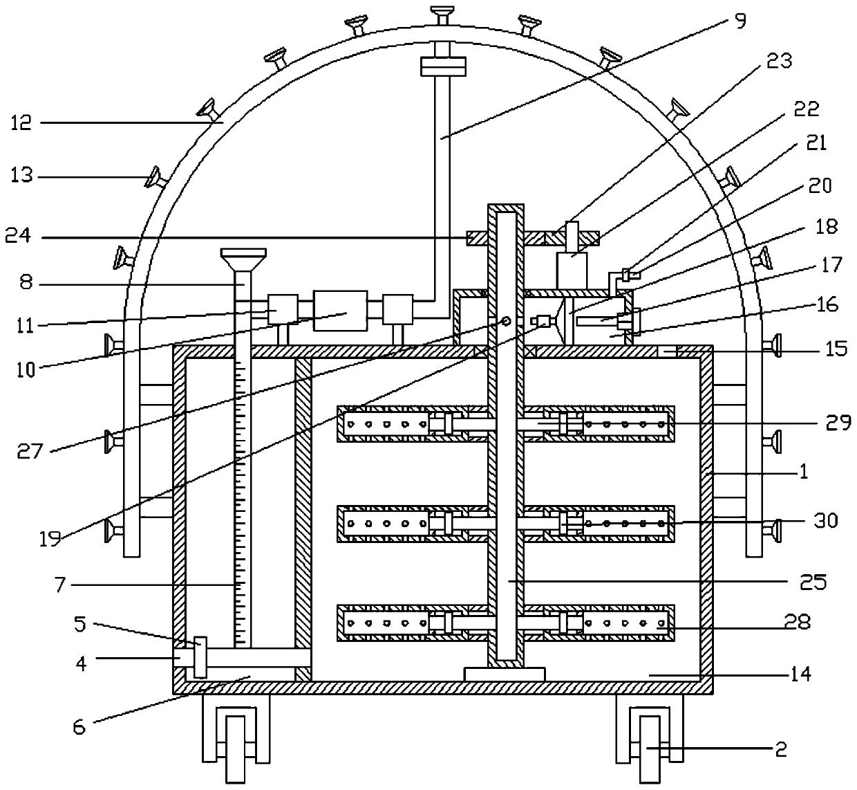
[0024] refer to Figure 1~3 , in the embodiment of the present invention, a simple platform for automatic constant temperature maintenance of the second lining of the tunnel, including a box body 1, the four corners of the lower side of the box body 1 are fixedly equipped with rollers 2, which can facilitate the movement of the equipment, and the left end of the box body 1 is provided with Groove 6, the lower end of the groove 6 is provided with an outlet pipe 4, the left end of the outlet pipe 4 is provided with a solenoid valve 5, which can control the discharge of water, and the upper side of the outlet pipe 4 is provided with a water level measuring tube 7, which can be used to detect the storage inside the equipment Water quantity, water level measuring tube 7 upper side is equipped with water adding pipe 8, can add aqueous solution conveniently, is positioned at the water level measuring tube 7 right side of box body 1 upper side and is provided with suction pipe 9, is eq...

Embodiment 2

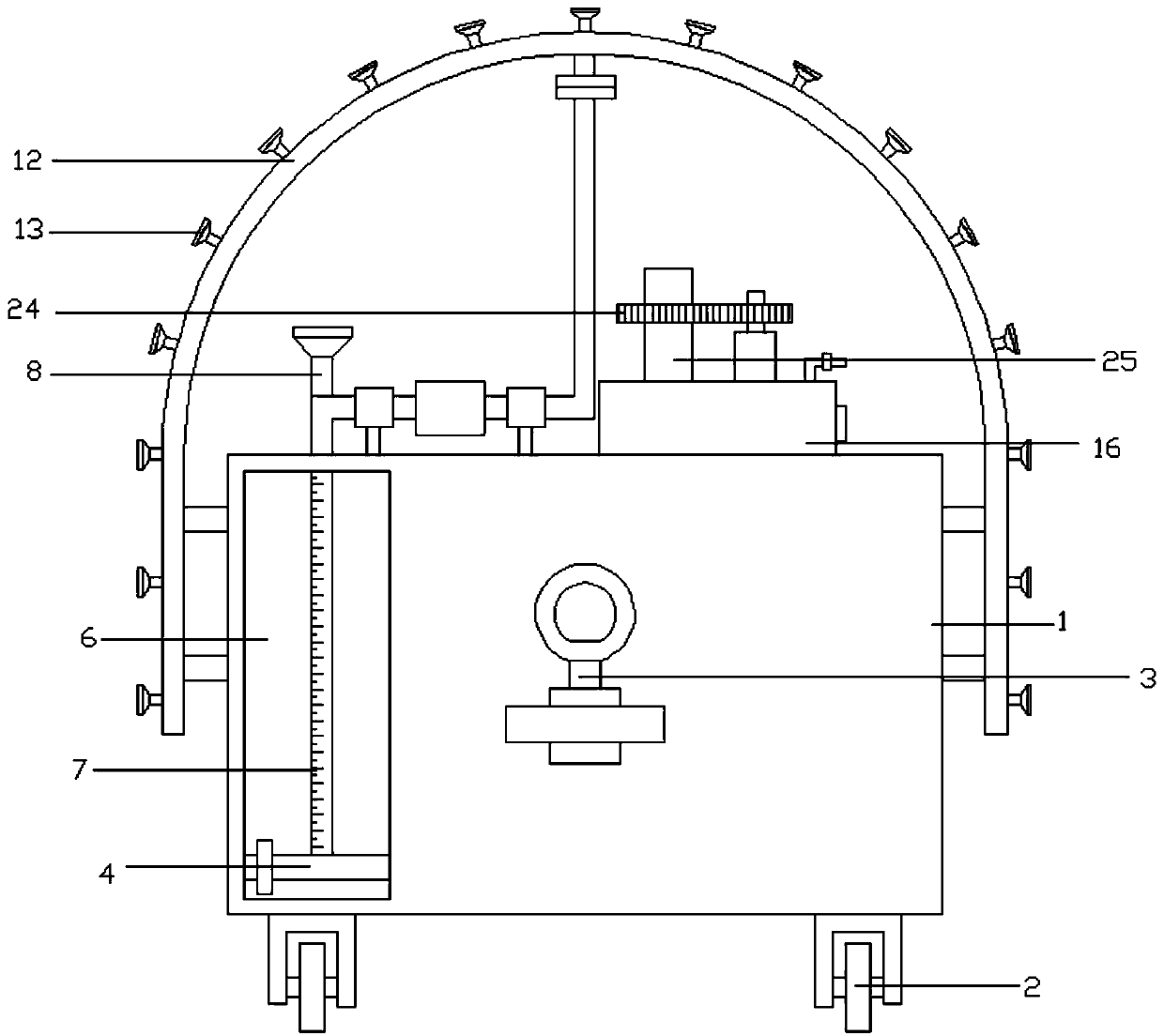
[0027] The difference from the first embodiment is that the middle part of the front side of the box body 1 is provided with a connecting piece 3, which can be connected with the power equipment, which can facilitate the movement of the equipment and reduce manpower and material resources.


PUM


Abstract

The invention relates to a large range, concretely to a tunnel secondary lining automatic constant temperature maintenance simple bench. The simple bench includes a box. Rolling wheels are fixedly mounted on the four corners of the lower side of the box. A groove is arranged in the left end of the box. A water outlet pipe is arranged on the lower end of the groove. A solenoid valve is arranged onthe left end of the water outlet pipe. A water level measuring pipe is arranged on the upper side of the water outlet pipe. A water pumping pipe is arranged on the right side of the water level measuring pipe on the upper side of the box. A water pump is mounted on the water pumping pipe. Fixed parts are mounted on the water pumping pipe on the left and right sides of the water pump. The upper side of the water pumping pipe is connected to a water spray pipe through a connection flange. The inner side of the lower end of the water spray pipe is connected to the box through fixing rods. Nozzlesare arranged on the outer side of the water spray pipe. A water storage cavity is arranged on the right side of the box. A vent is arranged in the right end of the top of the water storage cavity. Arotary aeration device is arranged on the upper side of the box. The tunnel secondary lining automatic constant temperature maintenance simple bench can facilitate heating treatment of equipment, canensure the automatic constant temperature maintenance of a tunnel secondary lining and facilitates the use of people.

Description

technical field [0001] The invention relates to a relatively large range, in particular to a simple platform for automatic constant temperature maintenance of the second lining of a tunnel. Background technique [0002] A tunnel is an engineering building buried in the ground, and it is a form of human use of underground space. Tunnels can be divided into traffic tunnels, hydraulic tunnels, municipal tunnels, and mine tunnels. The structure of the tunnel includes two parts: the main building and the auxiliary equipment. The main building is composed of the tunnel body and the tunnel door. The auxiliary equipment includes car avoidance tunnels, fire protection facilities, emergency communication and waterproof and drainage facilities. The long tunnel also has special ventilation and lighting equipment. [0003] The second lining is a term in tunnel construction. When the tunnel is excavated, it is driven forward along the face of the tunnel, and then the four sides of the tu...

Claims


Application Information

Patent Timeline
IPC IPC(8): E21D11/10F24H3/04F24H1/18
CPCE21D11/10F24H1/18F24H3/04
Inventor 邵炜星李栋伟查文华李明东王升福薛凯喜顾连胜胡鹏李雪芹
Owner EAST CHINA UNIV OF TECH
Why Eureka
Eureka Blog
Learn More