A magnetic fluid thrust cylindrical roller bearing and its processing technology

A cylindrical roller bearing and processing technology, applied in the direction of bearings, shafts and bearings, bearing components, etc., can solve the problems of low working noise, locked bearings, and become engineering hidden dangers, achieve micro-vibration bearing capacity, and reasonable structural design. , the effect of high load carrying capacity

Active Publication Date: 2020-08-04
NANCHANG INST OF TECH
View PDF5 Cites 1 Cited by
  • Summary
  • Abstract
  • Description
  • Claims
  • Application Information

AI Technical Summary

Problems solved by technology

[0004] Traditional bearing lubricants and their lubricating elements decay with time, and the uncontrollability of the decay process can easily cause the bearing to lock up, which may lead to serious consequences. The unpredictable service life of the bearing has gradually become an engineering hidden danger
[0005] The magnetic fluid lubricant in the case of an external magnetic field can significantly reduce the friction and wear in the mechanical system, and compared with the traditional lubrication bearing, the magnetic fluid lubricated bearing has low noise and high temperature resistance, and the magnetic fluid lubricating oil film also has A certain vibration-absorbing ability can also greatly reduce friction loss and surface wear, and even eliminate wear, which is very beneficial to improving the stability and running accuracy of the bearing. However, the magnetic field in the existing magnetic fluid thrust cylindrical roller bearing is difficult. The distribution control and the magnetic fluid cannot be evenly distributed inside the rolling bearing raceway, which seriously affects the engineering application of the magnetic fluid bearing. Therefore, further improvement is needed

Method used


Image

  • A magnetic fluid thrust cylindrical roller bearing and its processing technology
  • A magnetic fluid thrust cylindrical roller bearing and its processing technology
  • A magnetic fluid thrust cylindrical roller bearing and its processing technology

Examples


Embodiment Construction

[0031] The following will clearly and completely describe the technical solutions in the embodiments of the present invention with reference to the accompanying drawings in the embodiments of the present invention. Obviously, the described embodiments are only some, not all, embodiments of the present invention. Based on the embodiments of the present invention, all other embodiments obtained by persons of ordinary skill in the art without making creative efforts belong to the protection scope of the present invention.

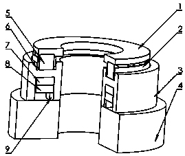
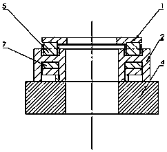
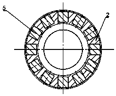
[0032] see Figure 1~3 , in an embodiment of the present invention, a magnetic fluid thrust cylindrical roller bearing comprises, from top to bottom, a shaft ring 1, a roller cage 2, a seat ring 3 and a stationary frame 4, and the middle part of the roller cage 2 The rollers 5 are arranged in sequence, and the roller cage 2 and the rollers 5 are set together in the annular raceway above the raceway 3, and the annular raceway of the raceway 3 is injected with a...


PUM


Abstract

The invention relates to the technical field of roller bearings, and discloses a magnetic fluid thrust cylindrical roller bearing, which comprises a shaft ring, a roller cage, a seat ring and a stationary frame from top to bottom, and the middle part of the roller cage is sequentially The rollers are arranged, and the roller cage and the rollers are arranged in the annular raceway above the seat ring, and the magnetic fluid is injected into the annular raceway of the seat ring, and the annular groove below the seat ring is provided with an annular gasket and an annular ring. Axial permanent magnet; its processing technology is also disclosed. In the present invention, the magnetic fluid is used as the thrust bearing lubricant, which can realize the bearing operation requirements of low friction, micro-vibration and high bearing capacity, and the seat ring is set as an annular raceway for the magnetic fluid and roller lubrication system, and the permanent The magnet is set at the lower part of the magnetic fluid as an external magnetic field application source, and the structure design is reasonable, which is especially suitable for precision instruments with strict operating conditions.

Description

technical field [0001] The invention relates to the technical field of roller bearings, in particular to a magnetic fluid thrust cylindrical roller bearing and its processing technology. Background technique [0002] Roller bearings are a type of rolling bearings and are one of the most widely used components in modern machinery. It relies on the rolling contact between the main elements to support the rotating parts. Roller bearings are now mostly standardized. Roller bearings have the advantages of small starting torque, high rotation accuracy, and convenient selection. Rolling bearings are divided into ball bearings and roller bearings according to rolling elements. [0003] Roller bearings rely on the rolling contact between the main parts to support the rotating parts. Different roller bearings can withstand different radial and axial forces. When selecting roller bearings, the selection should be made according to the specific working conditions. Roller bearings ...

Claims


Application Information

Patent Timeline
Patent Type & Authority Patents(China)
IPC IPC(8): F16C32/04F16C32/06F16C33/38F16C33/58B23P15/00
CPCB23P15/003F16C32/0417F16C32/0637F16C33/583Y02T10/86
Inventor 胡瑞熊乐许春霞熊震朱春生洪琦晏建武李彧雯邹凌云杨小品金萌赵希银江剑峰
Owner NANCHANG INST OF TECH
Why Eureka
Try Eureka