A system and method for cooperating heat supply with heat and electricity in a gas-fired thermal power plant

A technology of thermoelectric synergy and heating system, applied in the energy field, can solve the problems of unstorage, waste, insufficient power supply, etc., and achieve the effect of reducing the peak-to-valley difference of the power grid, alleviating the peak-to-valley difference, and avoiding heat waste.

Active Publication Date: 2021-08-27
北京热科能源技术研究有限公司
View PDF5 Cites 0 Cited by
  • Summary
  • Abstract
  • Description
  • Claims
  • Application Information

AI Technical Summary

Problems solved by technology

[0004] The purpose of the present invention is to provide a heat-electricity cooperative heat supply system and method for a gas-fired thermal power plant to solve the problems of insufficient power supply during the peak period of power consumption of the current gas-fired power plant and waste of power due to unstored power during the low-peak period of power consumption

Method used


Image

  • A system and method for cooperating heat supply with heat and electricity in a gas-fired thermal power plant
  • A system and method for cooperating heat supply with heat and electricity in a gas-fired thermal power plant
  • A system and method for cooperating heat supply with heat and electricity in a gas-fired thermal power plant

Examples


Embodiment 1

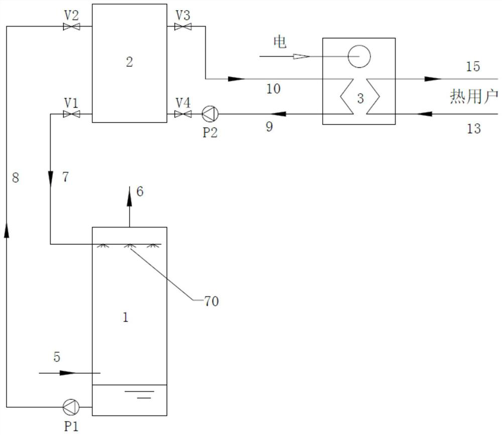
[0055] Embodiment 1 provides the most basic cogeneration heat supply system of a gas-fired thermal power plant, and its structure will be described in detail below.

[0056] refer to figure 1 , the heat-electricity collaborative heating system of the gas-fired thermal power plant includes a heat exchange energy storage system, an electric heat regulation system and a heating network heating system.

[0057] Wherein, the heat exchange energy storage system includes a heat exchanger 1, a heat storage tank 2, a first cold water supply pipe 7, a first hot water return pipe 8, a first circulation pump P1, a first valve V1 and a second valve V2,

[0058] The lower part and the top of the heat exchanger 1 are respectively provided with a flue gas inlet 5 and a flue gas outlet 6, the flue gas inlet 5 is used to communicate with the tail flue of the waste heat boiler of the gas-fired power plant, and the flue gas outlet 6 is used to discharge the inside of the heat exchanger 1 rising ...

Embodiment 2

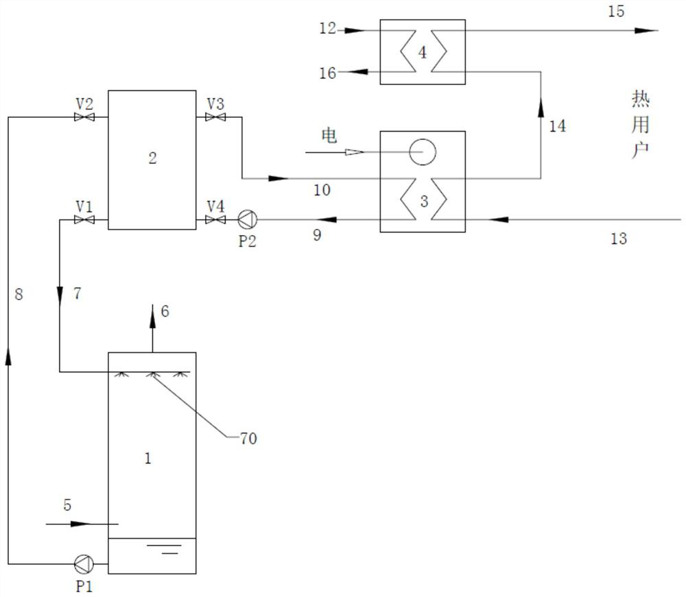
[0071] On the basis of embodiment 1, in order to further improve the heating capacity of the low-temperature return water of the heating network pipeline, embodiment 2 adds a heating network heater 4, and its connection relationship will be described in detail below.

[0072] refer to figure 2 , the cascade heating device also includes a heat network heater 4, and the heat network heater 4 is an existing mature technology, which is divided into various forms such as a steam-water heat exchanger or a water-water heat exchanger, and the preferred shell in embodiment 2 Tubular steam-water heat exchanger, the shell-and-tube steam-water heat exchanger includes steam inlet, condensate outlet, steam side exhaust pipe, heated water outlet, heated water inlet and water side exhaust pipe, etc.

[0073] As a specific implementation, the heating side of the heating network heater 4 is provided with a steam inlet and a condensate outlet, and the heated side of the heating network heater 4...

Embodiment 3

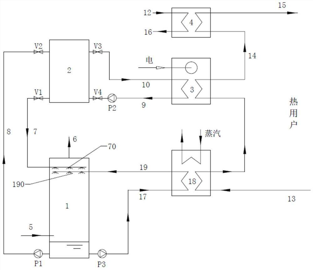
[0078] On the basis of Example 2, in order to improve the heat exchange efficiency of the flue gas in the heat exchanger 1 and improve the heating capacity of the low-temperature return water in the heating network pipeline, a spray circulation system and an absorption heat pump 18 are added in Example 3, as follows Describe its connection relationship in detail.

[0079] refer to image 3 , the cascade heating device also includes an absorption heat pump 18, which includes an evaporator, a condenser, an absorber, and a generator, etc., wherein the heat network return cold water pipe 13 can be connected with the absorption heat pump 18 absorber, and It can be connected with the condenser, and the outlet of the absorber or the condenser of the absorption heat pump 18 is connected with the inlet of the condenser of the electric heat pump 3 . Specifically, the cooling water return pipe 13 of the heat network is connected with the absorber inlet of the absorption heat pump 18, th...


PUM


Abstract

The invention discloses a heat-electricity cooperative heat supply system and method of a gas-fired thermal power plant. The system includes a heat exchange energy storage system, an electric heat regulation system and a heating network heating system. The return cooling water pipe is connected with the heat exchanger to form a heat exchange and energy storage circulation loop. The heat storage tank forms an electric heat regulation circulation loop through the second hot water supply pipe and the second return cooling water pipe and the electric heat pump, and the cascade heating device including the electric heat pump 1. The hot water supply pipe of the heating network and the cooling water return pipe of the heating network constitute a heating system of the heating network; the method includes heat storage in a heat storage tank and operation regulation of an electric heat pump. A heat-electricity cooperative heating system of a gas-fired thermal power plant disclosed by the present invention can effectively recover the exhaust heat of waste heat boilers in a gas-fired thermal power plant, and use the recovered flue gas heat to heat the water in the heating network, thereby improving the heat supply capacity of the thermal power plant, and at the same time, through the electric heat pump Cooperating with the adjustment of the heat storage tank, it can alleviate the peak-valley difference of the power grid load during the power peak period of the thermal power plant and the power trough period.

Description

technical field [0001] The invention relates to the field of energy, and in particular to a thermoelectric coordinated heating system and method for a gas-fired thermal power plant. Background technique [0002] Gas-fired power generation is the process of using natural gas or other combustible gases to generate heat to generate electricity. Since gas turbines entered the stage of power generation industry in the 1950s, gas-fired thermal power plants have achieved tremendous development worldwide and accumulated valuable experience by virtue of their advantages of high power generation efficiency and high thermal efficiency. Among them, the experience of European and American countries shows that it is necessary to install a gas turbine generator set with a power share of 8% to 10% in the power grid in view of the requirements of safety and peak regulation. The experience of our country also shows that the peak-to-valley difference of power grids in many areas of our countr...

Claims


Application Information

Patent Timeline
Patent Type & Authority Patents(China)
IPC IPC(8): F24D3/18F24D19/10
CPCF24D3/18F24D19/1015F24D19/1039
Inventor 张世钢苗青陈春寅
Owner 北京热科能源技术研究有限公司
Why Eureka
Try Eureka