
Method for constructing actual machining curve of small-curvature part based on point cloud boundaries

A technology for processing curves and point cloud boundaries, applied to computer parts, electrical components, 3D modeling, etc., can solve problems such as poor consistency, wavy boundary curves, sharp corners or rounded corners, etc., to ensure shape Features and size parameters, to meet the quality of surface processing, to ensure the effect of consistency

Active Publication Date: 2019-10-18
HUAZHONG UNIV OF SCI & TECH
View PDF3 Cites 17 Cited by
  • Summary
  • Abstract
  • Description
  • Claims
  • Application Information

AI Technical Summary

Problems solved by technology

[0005] The point cloud data boundary is limited by the accuracy of the scanner itself. The imaging principle and imaging quality are easily affected by the surface quality of the part and the reflective characteristics. The formed point cloud boundary itself is easy to form jagged. After fitting and interpolating the Nurbs curve , the boundary curve is prone to wavy, these characteristics also lead to inaccurate measurement based on point cloud data, poor consistency, and the extracted boundary curve cannot provide a reference on the trajectory for subsequent machining
[0006] At present, for the actual processing curve of the parts to be processed, there are the following problems: 1) The collected point cloud data is not used as a guide to obtain the actual processing curve; The fitting error of the processing curve at the corner and the sharp corner cannot be controlled, resulting in the cutting of the sharp corner or rounded corner; 3) Using third-party software to plan the actual processing curve requires communication with the third-party software, which is costly and difficult to program. complex

Method used


Image

  • Method for constructing actual machining curve of small-curvature part based on point cloud boundaries
  • Method for constructing actual machining curve of small-curvature part based on point cloud boundaries
  • Method for constructing actual machining curve of small-curvature part based on point cloud boundaries

Examples


Embodiment Construction

[0040] In order to make the object, technical solution and advantages of the present invention clearer, the present invention will be further described in detail below in conjunction with the accompanying drawings and embodiments. It should be understood that the specific embodiments described here are only used to explain the present invention, not to limit the present invention. In addition, the technical features involved in the various embodiments of the present invention described below can be combined with each other as long as they do not constitute a conflict with each other.

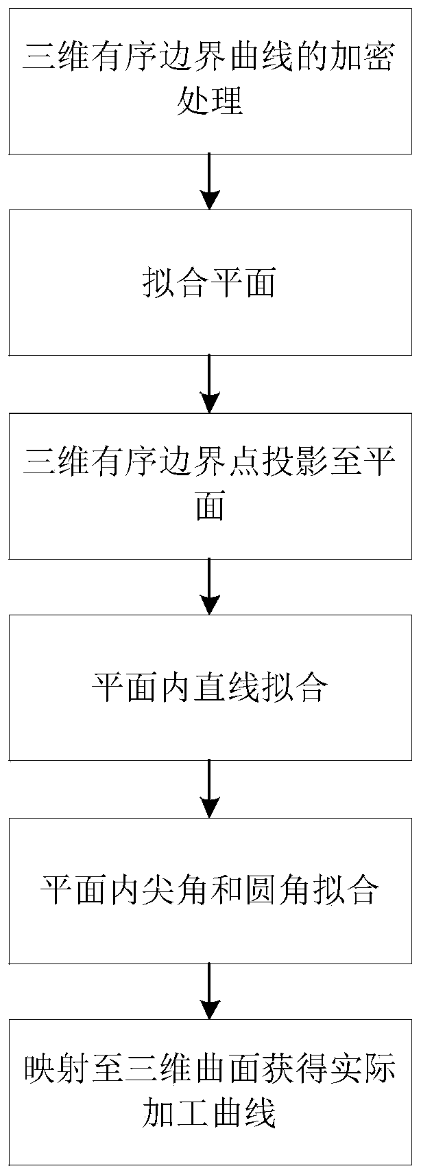
[0041] Such as figure 1 As shown, a method for constructing the actual processing curve of a small curvature part based on the point cloud boundary is characterized in that the method includes the following steps:

[0042] (a) For the three-dimensional ordered boundary curve of the part to be processed, the curve includes a plurality of ordered boundary points, and the three-dimensional ordered b...


PUM


Abstract

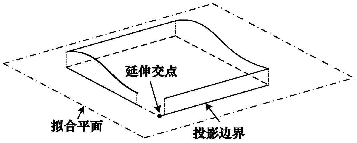
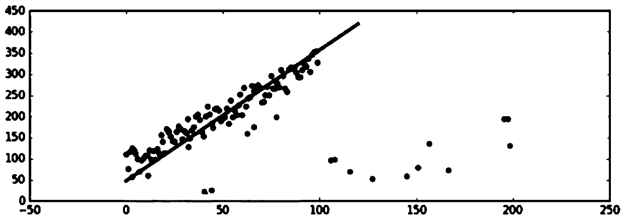
The invention belongs to the field of robot vision detection, and discloses a curve discretization method based on point cloud boundary geometrical characteristics. The curve discretization method comprises the following steps: (a) encrypting a three-dimensional ordered boundary curve of a part to be processed; (b) fitting the encrypted boundary points into a plane, and projecting each boundary point into the plane to obtain a projection point; (c) carrying out straight line Euclidean clustering and line point sets in a plane, and fitting the obtained point sets into a straight line; (d) carrying out Euclidean clustering on the projection points which are not fitted into the straight line to obtain a corner point set, and carrying out sharp corner or round corner fitting on the corner point set to obtain a fitted boundary curve in a plane; and (e) mapping the fitted boundary curve to the curved surface of the three-dimensional ordered boundary curve to obtain the actual machining curveof the to-be-processed part. By means of the curve discretization method, the actual machining curve is obtained through the point cloud data of the to-be-machined part, and sharp corner and round corner characteristics are reserved, and the machining precision is high.

Description

technical field [0001] The invention belongs to the field of robot vision detection, and more specifically relates to a curve discretization method based on geometric features of point cloud boundaries. Background technique [0002] Point cloud boundary geometric features are an integral part of point cloud features. Automatic segmentation, extraction, reconstruction and discretization of boundary curve features are the prerequisites for automatic measurement, virtual assembly and automatic processing of thin-walled parts with small curvature. At present, the conventional point cloud boundary feature extraction is divided into two methods: [0003] The surface reconstruction method directly obtains the boundary feature lines, and the boundary feature points can be obtained after the boundary feature lines are discretized. It is characterized in that firstly, the target point cloud data is segmented based on the local features of the surface, and then the subdivided local po...

Claims


Application Information

Patent Timeline
Patent Type & Authority Applications(China)
IPC IPC(8): G06T17/00G06K9/62
CPCG06T17/00G06F18/23213G06T17/30G06T2210/56G06F30/10G06F30/17H04L9/0894G06V10/763G06F18/2321G09C1/00
Inventor 李文龙彭泽龙蒋诚王刚
Owner HUAZHONG UNIV OF SCI & TECH
Learn More