Voltage reduction circuit

A technology of step-down circuit and filter capacitor, which is applied in the direction of electrical components, adjustment of electric variables, high-efficiency power electronic conversion, etc., can solve the problems of MOS tube damage, high voltage spikes, etc., suppress voltage spikes, improve circuit efficiency, and have a simple structure Effect

Inactive Publication Date: 2019-10-18
LEIHUA ELECTRONICS TECH RES INST AVIATION IND OF CHINA
View PDF4 Cites 0 Cited by
  • Summary
  • Abstract
  • Description
  • Claims
  • Application Information

AI Technical Summary

Problems solved by technology

[0003] During the turn-off process of the power switch tube of the existing step-down circuit, due to the existence of parasitic inductance of the line, a very high voltage spike is generated between the input terminal and the output terminal of the MOS tube, which will cause damage to the MOS tube in severe cases

Method used


Image

  • Voltage reduction circuit
  • Voltage reduction circuit
  • Voltage reduction circuit

Examples


Embodiment Construction

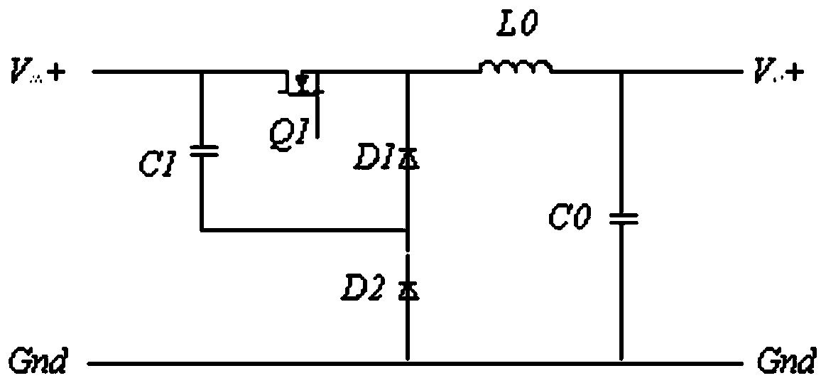
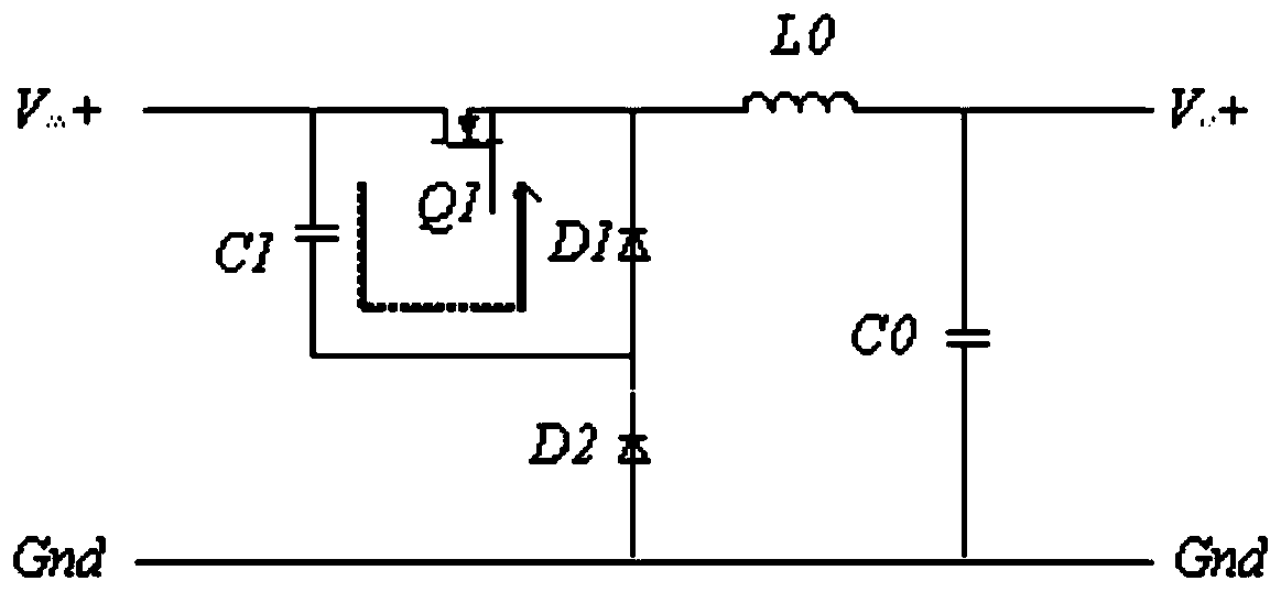
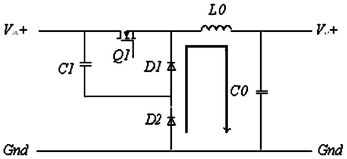
[0031] The application will be further described in detail below in conjunction with the accompanying drawings and embodiments. It should be understood that the specific embodiments described here are only used to explain the related application, not to limit the application. In addition, it should be noted that, for ease of description, only parts relevant to the present application are shown in the drawings.

[0032] It should be noted that, in the case of no conflict, the embodiments in the present application and the features in the embodiments can be combined with each other. The present application will be described in detail below with reference to the accompanying drawings and embodiments.

[0033] It should be noted that in the description of this application, the terms "center", "upper", "lower", "left", "right", "vertical", "horizontal", "inner", "outer", etc. The terms of the indicated direction or positional relationship are based on the direction or positional ...


PUM


Abstract

The invention belongs to the technical field of voltage reduction circuit design, and particularly relates to a voltage reduction circuit. The voltage reduction circuit comprises an MOS transistor with the drain electrode connected with the positive electrode of an input power supply, a filter inductor with one end serving as the first end thereof and connected with the source electrode of the MOStransistor and the other end serving as the second end thereof and the output positive electrode of the voltage reduction circuit, a filter capacitor with one end serving as the first end thereof andconnected with the second end of the filter inductor and the other end serving as the second end thereof and the output negative electrode of the voltage reduction circuit, a first diode with the negative electrode connected with the source electrode of the MOS transistor, a second diode with the negative electrode connected with the positive electrode of the first diode and the positive electrode connected with the negative electrode of the input power supply, and a first capacitor with one end connected with the drain electrode of the MOS transistor and the other end connected with the positive electrode of the first diode.

Description

technical field [0001] The application belongs to the technical field of step-down circuit design, and in particular relates to a step-down circuit. Background technique [0002] The step-down circuit is a common non-isolated power electronic converter, which is widely used in various switching power supplies. [0003] During the turn-off process of the power switch tube of the existing step-down circuit, due to the existence of parasitic inductance of the line, a very high voltage spike is generated between the input terminal and the output terminal of the MOS tube, which may cause damage to the MOS tube in severe cases. [0004] The present application is proposed in view of the above-mentioned defects of the prior art. Contents of the invention [0005] The purpose of the present application is to provide a step-down circuit to overcome or alleviate at least one defect of the prior art. [0006] The technical scheme of the application is: [0007] A step-down circuit...

Claims


Application Information

Patent Timeline
Patent Type & Authority Applications(China)
IPC IPC(8): H02M3/155
CPCH02M3/155H02M1/0038H02M1/0048Y02B70/10
Inventor 龚坤珊戴钱坤王舸
Owner LEIHUA ELECTRONICS TECH RES INST AVIATION IND OF CHINA
Why Eureka
Try Eureka